Isolated inputs, Extending the input range – Measurement Computing CIO-PDISO8 User Manual
Page 15
CIO-PDISO8 User's Guide
Functional Details
14
Isolated inputs
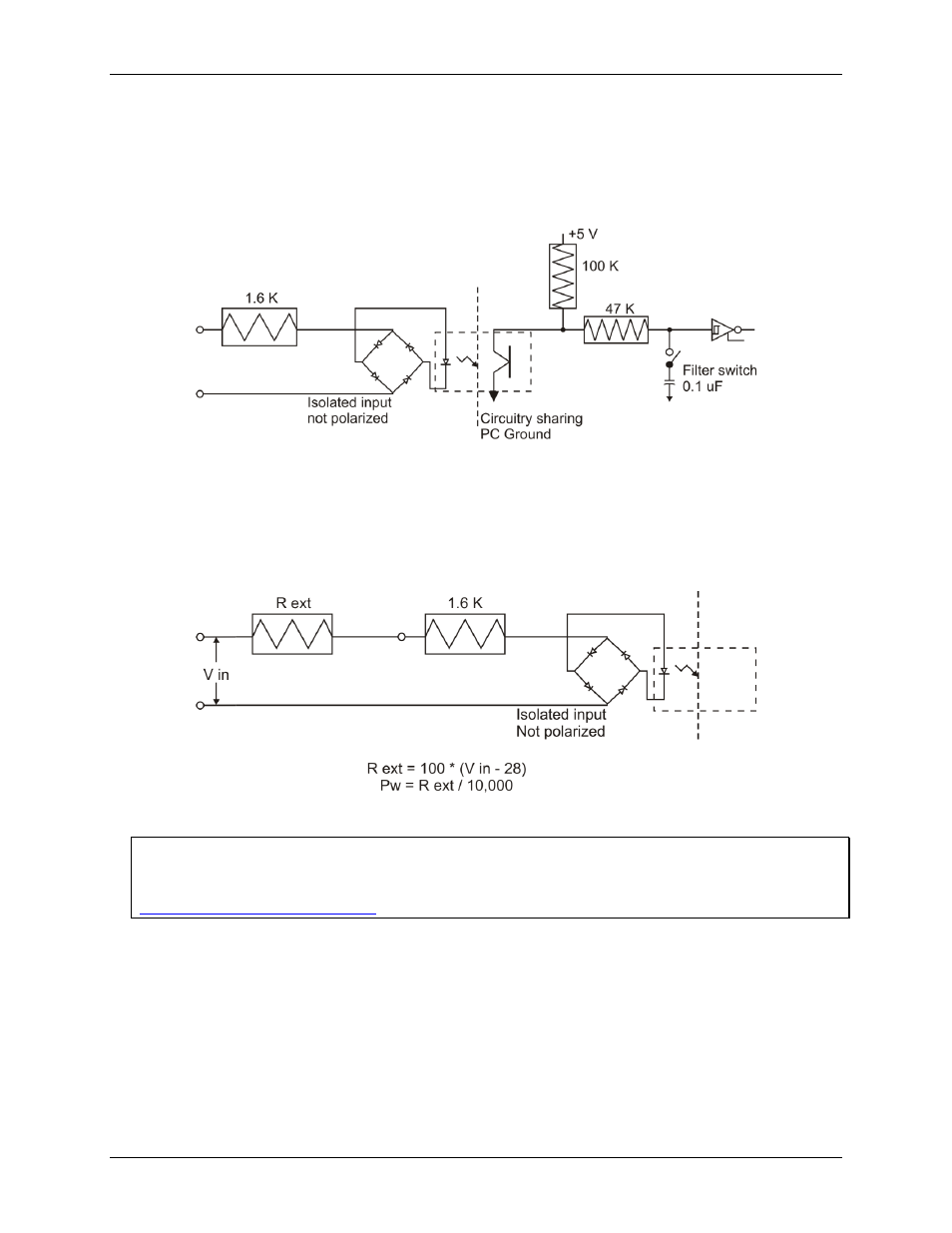
The CIO-PDISO8 has eight isolated input channels. A schematic of a single channel is shown in Figure 10. The
signals are routed through a bridge rectifier so that the inputs are not polarity sensitive.
Figure 10. Isolated input schematic - simplified
Extending the input range
To extend the input range beyond the 5-28V specified, add an external resistor. Figure 11 shows the resistor and
the equations used to calculate resistor values for a given Vin.
Figure 11. Input range-extending resistor
For more information on digital signal connections
For more information on digital signal connections and digital I/O techniques, refer to the Guide to Signal
Connections. This document is available on our web site at available on our web site at