Cabling, Cabling -6, Pin signal name – Measurement Computing PCI-DAS6402/16 User Manual
Page 14
PCI-DAS6402/16 User's Guide
Installing the PCI-DAS6402/16
Table 2-4. Auxiliary/digital connector pin out
Signal Name Pin
Pin Signal
Name
NC
40
•
•
•
•
39
NC
NC
38
•
•
•
•
37
DGND
FIRSTPORTA Bit 0
36
•
•
•
•
35
PC +5V
FIRSTPORTA Bit 1
34
•
•
•
•
33
DGND
FIRSTPORTA Bit 2
32
•
•
•
•
31
NC
FIRSTPORTA Bit 3
30
•
•
•
•
29
DGND
FIRSTPORTA Bit 4
28
•
•
•
•
27
NC
FIRSTPORTA Bit 5
26
•
•
•
•
25
DGND
FIRSTPORTA Bit 6
24
•
•
•
•
23
NC
FIRSTPORTA Bit 7
22
•
•
•
•
21
DGND
FIRSTPORTC Bit 0
20
•
•
•
•
19
FIRSTPORTB Bit 0
FIRSTPORTC Bit 1
18
•
•
•
•
17
FIRSTPORTB Bit 1
FIRSTPORTC Bit 2
16
•
•
•
•
15
FIRSTPORTB Bit 2
FIRSTPORTC Bit 3
14
•
•
•
•
13
FIRSTPORTB Bit 3
FIRSTPORTC Bit 4
12
•
•
•
•
11
FIRSTPORTB Bit 4
FIRSTPORTC Bit 5
10
•
•
•
•
9
FIRSTPORTB Bit 5
FIRSTPORTC Bit 6
8
•
•
•
•
7
FIRSTPORTB Bit 6
FIRSTPORTC Bit 7
6
•
•
•
•
5
FIRSTPORTB Bit 7
DGND
4
•
•
•
•
3
NC
PC +5V
2
•
•
•
•
1
NC
Bottom of board
↓
Cabling
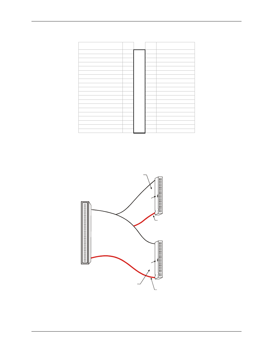
Use a C100FF-x 100-pin cable to connect signals to the PCI-DAS6402/16 board. This cable consists of two
50-pin ribbon cables that are joined together at a 100-pin high density header connector (
.)
Figure 2-1. C100FF-x cable
1
50
2
49
51
100
52
99
100
50
51
1
Key
Key
The red stripe
identifies pin # 1
The red stripe
identifies pin # 51
Cable is labeled
“Pins 51-100”
Cable is labeled
“Pins 1-50”
Field Wiring connections:
CIO-MINI50
CIO-MINI50/DST
CIO-TERM100
CIO-TERM100/DST
CIO-SPADE50
SCB-50
Field Wiring connections:
CIO-MINI50
CIO-MINI50/DST
CIO-TERM100
CIO-TERM100/DST
CIO-SPADE50
SCB-50
2-6