Measurement Computing PCI-DAS6402/16 User Manual
Page 15
PCI-DAS6402/16 User's Guide
Installing the PCI-DAS6402/16
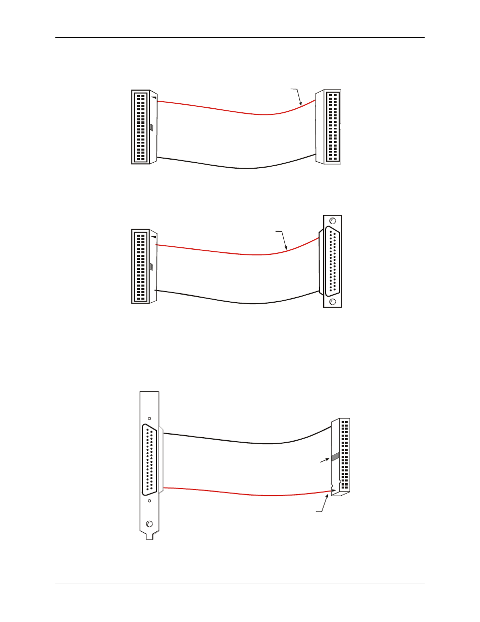
For signal connections and termination, you can use the CIO-MINI40 screw terminal board and C40FF-x cable.
For connections to 37-pin screw terminal boards, you can use the C40-37F-x cable.
The red stripe
identifies pin # 1
40-pin Female
IDC Connector
1
2
39
40
40-pin Female
IDC Connector
1
2
39
40
Figure 2-2. C40FF-x cable
20
1
37
19
The red stripe
identifies pin # 1
37-pin Female
Dsub Connector
40-pin Female
IDC Connector
1
2
39
40
Figure 2-3. C40-37F-x cable
For digital signal conditioning, you can connect the BP40-37 cable to a C37FF-x or C37FFS-x cable, and then
connect one of these cables to the 37-pin connector on MCC’s digital signal conditioning boards. Refer to page
2-9 for a list of compatible accessories.
37
19
20
1
The red stripe and arrow
identify pin # 1
2
40
1
39
Key
37-pin Male D Connector
with Backplate Assembly
40-pin Female
IDC Connector
Figure 2-4. BP40-37 cable
2-7