Pull-up/pull-down dip switches, Mechanical drawings – Measurement Computing USB-DIO96H-50 User Manual
Page 13
Advertising
USB-DIO96H/50 User's Guide
Functional Details
13
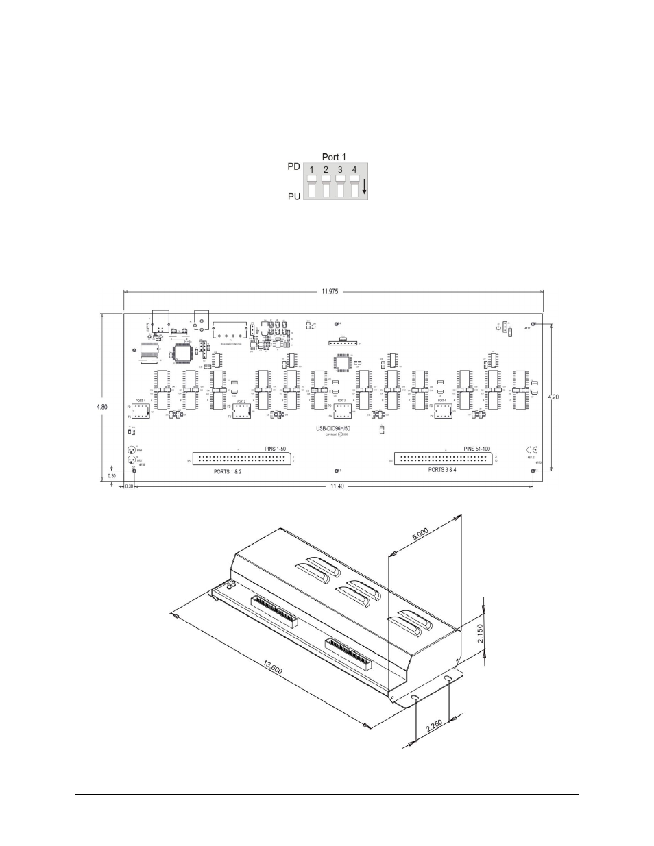
Pull-up/pull-down DIP switches
Use the on-board DIP switches labeled
PORT 1
through
PORT 4
to configure the pull-up/down configuration
for each port. Each set of DIP switches includes four switches labeled 1 to 4. Switch 1 controls PORTA, switch
2 controls PORTB, switch 3 controls PORTCL, and switch 4 controls PORTCH. Figure 6 shows the DIP
switches used to configure Port 1.
Figure 6. Pull-up/down switch configuration
All DIP switches are configured by default for pull-up (
PU
). To configure for pull-down slide the switch to the
PD
position.
Mechanical drawings
Figure 7. Circuit board dimensions
Figure 8. Enclosure dimensions
Advertising