Ch 4 - connectors, indicators, cables, & pinouts, Daqscan/2000 series hardware, Connectors, indicators, cables, & pinouts 4 – Measurement Computing DaqScan 2000 Series User Manual
Page 25
Connectors, Indicators, Cables, & Pinouts 4
DaqScan/2000 Series Hardware …… 4-1
Cables …… 4-3
Pinouts …… 4-5
DaqScan/2000 Series Hardware
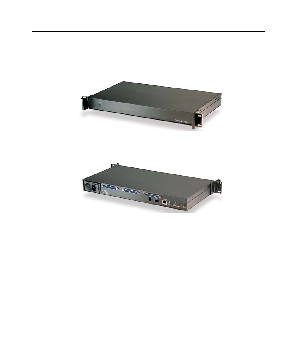
DaqScan Front Panel
Front Panel
The DaqScan/2000 Series front panels contain a power indicator LED. The power switch and
connectors are on the rear panel.
DaqScan/2001, Rear Panel
Rear Panel
The DaqScan/2000 Series rear panels each contain a Power Switch, AC power cord connector,
2 Synchronization jacks, a MAC Address Label, Ethernet connector, 5 LEDs [ 2 of which are on
the Ethernet connector], and a set of DB37 connectors. All four DaqScan models have P2 and
P3 connectors; but in addition, DaqScan/2001 and DaqScan/2005 have P1 connectors for
analog I/O.
P1 - DB37 Connector: P1 applies to DaqScan/2001 and DaqScan/2005 only. P1 is the
analog input port for 16 single-ended analog inputs or 8 differential, programmable on a per-
channel basis as single-ended or differential and as uni-polar or bipolar. The 3 programmable
ranges are from ±10 V to ±156 mV full scale. P1 can be used to connect the DaqScan to an
optional analog DBK card.
P2 - DB37 Connector: P2 is a general purpose digital I/O port with 24 (3 x 8-bit) lines on P2,
or digital I/O expansion port controlling up to 272 external lines. Programmable as input or
output. P2 can be used to connect to an optional digital DBK card.
P3 - DB37 Connector: 16-bit digital I/O port with 4 counter inputs and 2 timer outputs. In
addition, DaqScan/2001 and DaqScan/2004 each have a P3 connection to 4 analog outputs
(DAC0, DA1, DAC2, and DAC3).
DaqScan/2000 Series
898095
Connectors, Indicators, Cables, & Pinouts 4-1