Step 3 – configure boards, Configure boards – Measurement Computing ADAC/5500 Series Installation User Manual
Page 9
Step 3
– Configure Boards
WARNING
Always turn the computer power OFF and unplug it before connecting or disconnecting a screw
terminal panel or a cable to the PCI card. Failure to do so could result in electric shock, or
damage to equipment.
Before you can use your ADAC/5500 Series Board, you will need to configure it using the ADAC/5500 Series
User’s Manual, p/n 1107-0905 (ADAC5500 Series Users Manual.pdf) for reference. However, prior to doing so
you may find it helpful to review the following points:
All configurations, including data-acquisition settings such as analog input, data collection rates, input
voltage range, and operating modes are made through ADAC configuration software. The ADAC
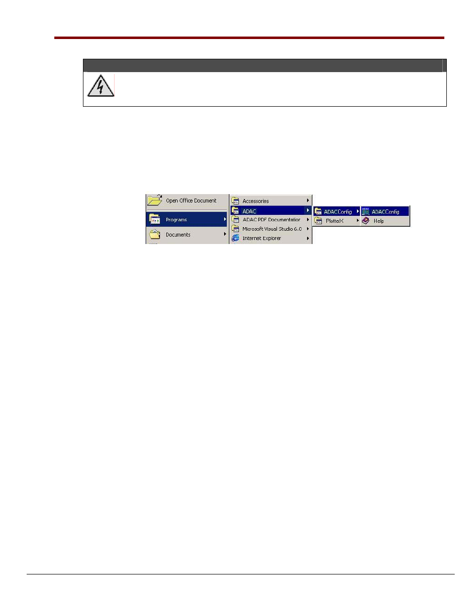
configuration software (ADAC Config) file can be accessed from the Windows desktop Start Menu by
navigating as follows:
Start
⇒ Programs ⇒ ADAC ⇒ ADAC Config ⇒ ADAC Config
Desktop Path to ADAC Config
•
ADAC ADLIB WDM software drivers provide an application level software interface to Windows
98/ME/NT/2000/XP. Software packages such as LabVIEW
™ communicate through our ADLIB
driver software. These packages configure and collect, or output, acquisition data in a GUI based
interface.
•
•
•
•
•
•
•
The ADAC/5501MF, ADAC/5502MF, ADAC/5503HR and ADAC/5504HR analog inputs are
impedance buffered and drive a differential gain amplifier that can be referenced in a number of ways,
allowing the following programmable input configurations: Single-Ended, Pseudo-Differential, and
Fully-Differential.
The ADAC/5500MF analog inputs are impedance buffered. They can only be referenced in Single-
Ended input configuration. 1 to 176 element channel-configuration RAM is provided to allow each
ADC channel to be programmed with a different combination of Gain, Range, and Input Configuration.
Note that these modes also apply to expansion channels located on the ADAC line of accessory screw
terminal panels.
The analog inputs on the ADAC/5500, ADAC/5501MF, ADAC/5502MF, ADAC/5503HR and
ADAC/5504HR may be configured for either
±10 V bipolar or 0-10 V unipolar operation. The input
range is programmable on a channel-by-channel basis in a 176-element channel configuration RAM.
Note that the range selection also applies to expansion channels.
The programmable gain circuitry on the ADAC/5501MF, ADAC/5502MF, ADAC/5503HR and
ADAC/5504HR must be taken into account in defining the usable error free input range. The boards
provide a wide range of programmable ranges and resolutions.
The ADAC/5500 Series Boards each bring out ±15 V and +5 V to the main I/O connector (J1). In
addition, the ADAC/5501MF, ADAC/5502MF, ADAC/5503HR and ADAC/5504HR bring +5 V to the
auxiliary digital I/O connectors (P3 and P5), located on the backside of those boards. These power lines
are individually fused to protect the ADAC/5500 Series Board. Note that connecting or disconnecting
cables or screw terminal panels (as well as any user connections to these power lines) may blow a fuse,
or cause damage to the board.
Incorrect connection of user wiring is one of the most common problems experienced by users of data
acquisition boards. To ensure proper results, you must first determine what type of signal source you are
measuring (Ground Referenced Source or Floating Source), and then choose the appropriate input
configuration on your data acquisition card (Differential, Pseudo-Differential, or Single-Ended). Your
user’s manual provides detailed information.
1107-0940, rev 2.0
908096
ADAC/5500 Series Installation Guide 9