Measurement Computing Digital HS User Manual
Page 53
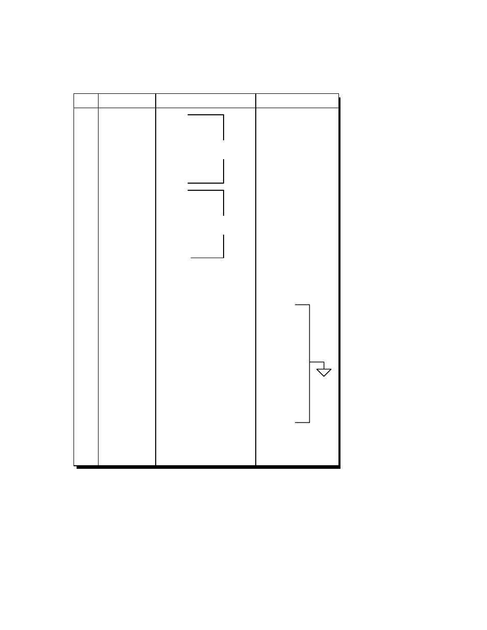
Digital Output Port Connector Pin Assignments
Pin Description
Direction
Designation
1
2
3
4
5
6
7
8
9
10
11
12
13
14
15
16
17
18
19
20
21
22
23
24
25
26
27
28
29
30
31
32
33
34
35
36
37
DOUT0
DOUT1
DOUT2
DOUT3
DOUT4
DOUT5
DOUT6
DOUT7
DOUT8
DOUT9
DOUT10
DOUT11
DOUT12
DOUT13
DOUT14
DOUT15
oEND
oDAV
oBusy
+5v
Common
Common
Common
Common
Common
Common
Common
Common
Common
Common
Common
Common
Common
/OE
oClear
oTrigger
/oRESET
Output - Tri-state
Output - Tri-state
Output - Tri-state
Output - Tri-state
Output - Tri-state
Output - Tri-state
Output - Tri-state
Output - Tri-state
Output - Tri-state
Output - Tri-state
Output - Tri-state
Output - Tri-state
Output - Tri-state
Output - Tri-state
Output - Tri-state
Output - Tri-state
Output
Output
Input
+Vcc
Ground
Ground
Ground
Ground
Ground
Ground
Ground
Ground
Ground
Ground
Ground
Ground
Ground
Input
Output
Output
Output
Bit 0
Bit 1
Bit 2
Bit 3
Bit 4
Bit 5
Bit 6
Bit 7
Bit 8
Bit 9
Bit 10
Bit 11
Bit 12
Bit 13
Bit 14
Bit 15
End Of Transfer Bit
Output Data Available
Output Busy
Logic Power
Logic Common
Logic Common
Logic Common
Logic Common
Logic Common
Logic Common
Logic Common
Logic Common
Logic Common
Logic Common
Logic Common
Logic Common
Logic Common
Output Tri-State Enable
Output Clear
Output Trigger
Output Reset
Second
Byte
First
Byte