4 i/o connector & pinout – Measurement Computing CIO-CTRxxHD User Manual
Page 8
4 I/O CONNECTOR & PINOUT
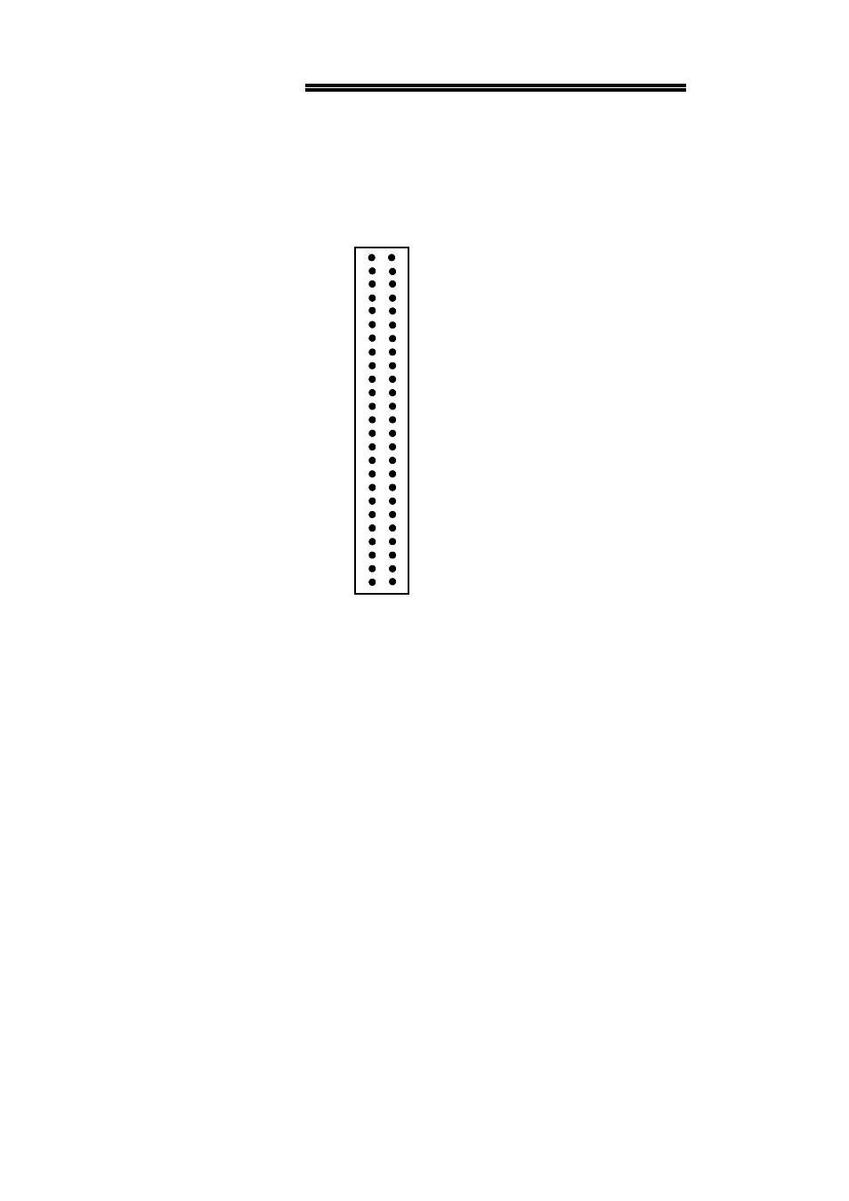
The CIO-CTRxxHD use a 50-pin inline connector. The CIO-CTR10HD has only one
connector while the CIO-CTR20HD has two. The connectors are compatible with the
optional C50FF-series cables and CIO-MINI50 screw terminal adapter board. The
pinout of these connectors is shown below.
NOTE:
Chip 1 (U1) is accessed at the bottom half of P1 (pins 1 - 22);
Chip 2 (U2) is the top half of P1 (pins 27 - 48);
Chip 3 (U3) is accessed at the bottom half of P2 (pins 1 - 22);
Chip 4 (U4) is the top half of P2 (pins 27 - 48).
4
CIO-CTRxxHD CONNECTOR
49
47
45
43
41
39
37
35
33
31
29
27
25
23
21
19
17
15
13
11
9
7
5
3
1
+5V
EXT SRC
GATE 5
CLK IN 5
GATE 4
CLK IN 4
GATE 3
CLK IN 3
GATE 2
CLK IN 2
GATE 1
CLK IN 1
+5 V
+5 V
EXT SRC
GATE 5
CLK IN 5
GATE 4
CLK IN 4
GATE 3
CLK IN 3
GATE 2
CLK IN 2
GATE 1
CLK IN 1
GND
FOUT
GND
CTR OUT 5
GND
CTR OUT 4
GND
CTR OUT 3
GND
CTR OUT 2
GND
CTR OUT 1
IR INPUT
GND
FOUT
GND
CTR OUT 5
GND
CTR OUT 4
GND
CTR OUT 3
GND
CTR OUT 2
GND
CTR OUT 1
8
6
50
48
46
44
42
40
38
36
34
32
30
28
26
24
20
18
16
14
12
10
22
4
2