2 interrupt & dma level select – Measurement Computing CIO-PDMAxx User Manual
Page 7
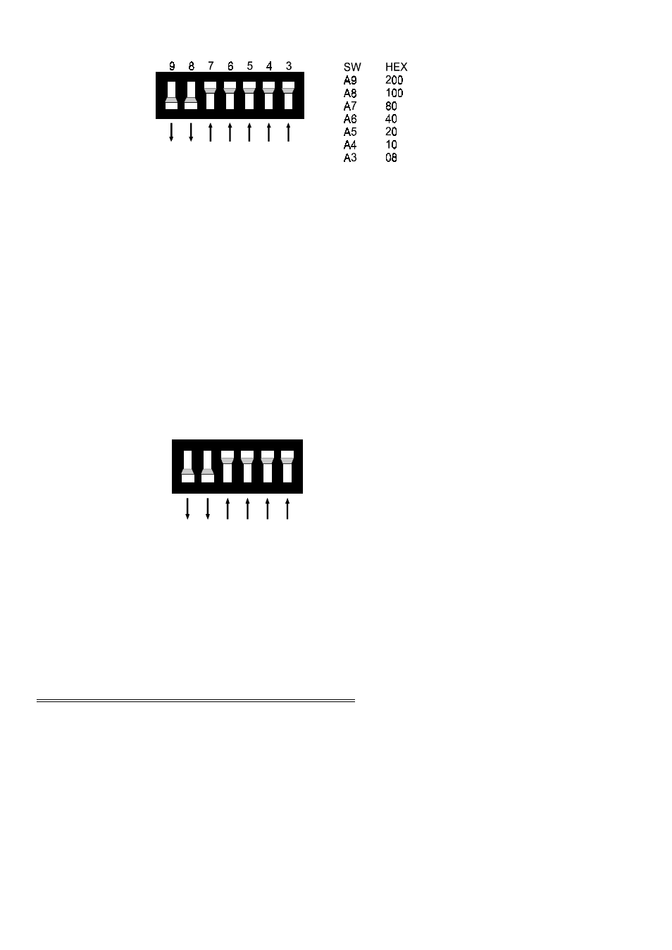
Figure 3-1. CIO-PDMA16 Base Address Switches (300h shown)
A complete address is constructed by calculating the hexadecimal number which
corresponds to all the address bits the CIO-PDMAx can respond to. The range of
base addresses are:
CIO-PDMA16
200h to 3F8h
CIO-PDMA32 200h to 3F0h
In the default configuration, shown in Figures 3-1 and 3-2, addresses 9 and 8 are
DOWN, and all others are UP. Address 9 = 200 hex (512 decimal) and address 8 =
100 hex (256 decimal). When added together they equal 300 hex (768 decimal).
Figure 3-2. CIO-PDMA32 Base Address Switches (300h shown)
NOTE: The CIO-PDMA32 has one fewer switch than the CIO-PDMA16.
NOTE
DISREGARD NUMBERS PRINTED ON THE SWITCH. REFER
ONLY TO WHITE NUMBERS PRINTED ON THE BOARD.
3.2 INTERRUPT & DMA LEVEL SELECT
The interrupt and DMA levels used by the CIO-PDMA boards are selected in
software. Refer to the documentation for the software package you are using to set
these parameters.
3
S W
A 9
A 8
A 7
A 6
A 5
A 4
H E X
20 0
10 0
80
40
20
10
9
8
7
6
5
4