Service and replacement parts, Continued) – Metro С5 8 Series Controlled Temperature Heated Holding Cabinets User Manual
Page 15
Advertising
13
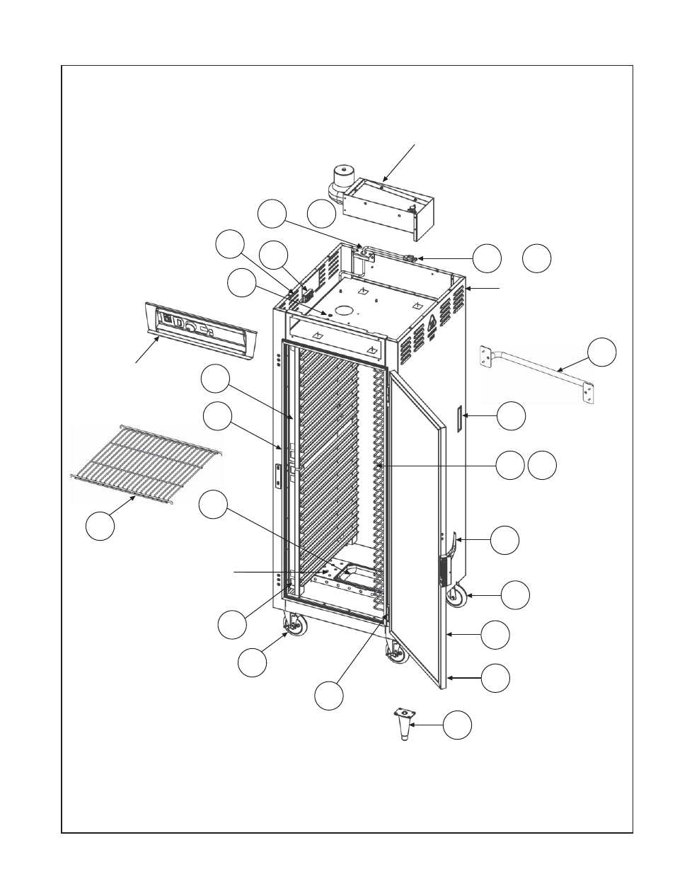
SERVICE and REPLACEMENT PARTS
(continued)
Replacement Parts Diagram
*For slide identifi cation, see pages 4 and 5.
STRAIGHT PLUG CORD SHOWN
24
14
25
18
15
22
*
20
23
CABINET BODY
8
9
10
11
21
*
13
19
CONTROL PANEL
See page 11.
FLOOR DUCT
17
16
AIR DUCT
See page 11.
or 8A
or 9A
26
27
28
28
Advertising
This manual is related to the following products: