3 configuration, 1 video (adc-sdi), 1 dip switches – Nevion AVA-MUX User Manual
Page 10
AVA-MUX
Rev. C
nevion.com | 10
3 Configuration
3.1 Video (ADC-SDI)
3.1.1 DIP switches
The configuration of the card can always be changed from the GYDA system controller but
may also be configured with DIP switches. Most users will set all switches OFF except
switches 1 and 10.
3.1.1.1 Manual mode
DIP switch 1 should be in the ON position if the card is to be controlled with the other DIP
switches. If the switch is OFF then the card starts with the stored configuration and the other
switches are ignored. GYDA is always able to re-configure the card but the new configuration
will only be remembered if switch 1 is OFF.
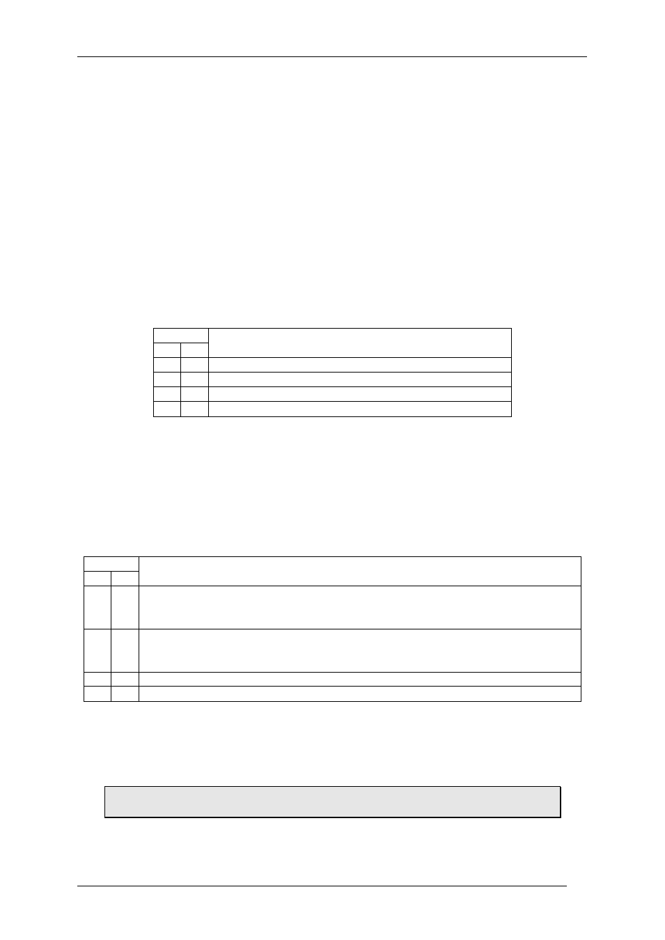
3.1.1.2 Video input mode
DIP switches 2 and 3 configure the input channel selection modes as shown in the table.
Switch
Output Video Mode
3
2
0
0
Auto detect. The first valid detected signal is used.
0
1
CVBS on input 1.
1
0
CVBS on input 2.
1
1
YC or (S-Video, SVHS) on inputs 1 and 2.
3.1.1.3 EDH packet disable
DIP switch 4 should be in the ON position if the SDI signal must not contain an EDH packet.
3.1.1.4 Field 1 marking disable
DIP switch 5 should be switched ON if the SDI signal must not have a field 1 marker on line
7.
3.1.1.5 Decoder filter selection
DIP switch 6 and 7 are used to select the decoder filter used, as shown in the following table.
The ADC-SDI has two adaptive filters, a comb filter and a low pass/ notch filter set.
Switch
Decoder filter
7
6
0
0
Default. Adaptive 3-line comb filter selection.
NTSC adaptive comb with filter coefficients (¼, ½, ¼), PAL adaptive comb with
filter coefficients (½, 0, ½)
0
1
Adaptive 3-line comb filter selection with optional filter coefficients.
NTSC adaptive comb with filter coefficients (½, 0, ½), PAL adaptive comb with
filter coefficients (¼, ½, ¼)
1
0
Fixed 2-line comb filter.
1
1
Luminance filtered with chroma trap notch. Chroma low pass filtered.
3.1.1.6 Restore factory settings
DIP switch 8 should be used if the card is to be reset to the factory configuration. This will
also reset the delay parameters to zero. The card is reset when the card is powered up with
this switch set ON. DIP switch 8 should be set back to the OFF position and the card should
then be reset.
The reset button at the front of the card may be used instead of removing the
card or switching the power supplies on and off.