5 operation, 1 adc-sdi leds, 2 aav-sd-xmux leds – Nevion AVA-MUX User Manual
Page 20
AVA-MUX
Rev. C
nevion.com | 20
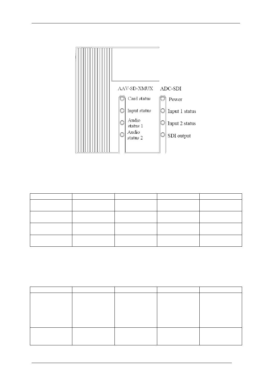
5 Operation
Figure 7: AVA-MUX LEDs
(Text not printed on the front panel). Each module has 4 LED’s. The colors of each of the
LED’s have different meanings as shown in the tables below.
5.1 ADC-SDI LEDs
Diode \ state
Red LED
Orange LED
Green LED
No light
Power
Major error.
Remove module
n/a
Module power is
OK
Module has no
power
Input 1 status
Video signal
absent.
Signal detected
but not locked
No signal
Channel inactive
Input 2 status
Video signal
absent.
Signal detected
but not locked
No signal
Channel inactive
SDI output
Errors detected
n/a
No errors
detected
5.2 AAV-SD-XMUX LEDs
AES status LEDS show information decided by DIP switch 2.7- LED mode.
‘On’ corresponds to the audio input mode and is the preferred setting in the AVA-MUX.
‘Off’ corresponds to the de-embedder audio mode.
Diode \ state
Red LED
Orange LED
Green LED
No light
Card status
PTC fuse has
been triggered
or FPGA
programming
has failed or
laser has failed
Module has not
been
programmed
Module is OK
Module has no
power
SDI input
status
Video signal
absent.
Electrical video
signal present
Optical video
signal Present
Module has not
been
programmed