Obvius A89DC-08 User Manual
Page 6
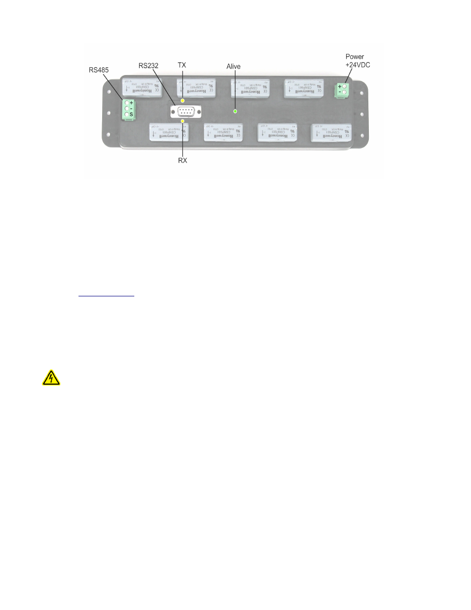
Power and Communication Connections
Hardware Installation
Step 1 - Unpack materials: Remove all materials from shipping box and verify all required components are available
Step 2 - Mount the A89DC-08 inside the electrical enclosure. Be sure to provide enough room to route the load wires
through the hall effect sensor openings.
Step 3 – Attach the power supply to the A89DC-08. Be sure to observe the polarity. Note: Power can be disconnected by
removing the screw terminal plug from the A89DC-08 power connection socket.
Step 4 - Connect the RS485 Modbus network loop as shown in the wiring diagram. Follow the manufacturer’s instructions
for installing and powering the Modbus Master device. Verify that the Modbus address settings are unique for each device
(i.e., no two devices with the same address). Connect each device in the chain by “daisy-chaining” the devices together .
Observe + and - polarity on the Modbus devices. For more information about Modbus loops, please read our Modbus FAQ
available at
Do not ground the RS485 shield inside the electrical panel. All RS485 and 24vdc power wires, including the shield should
be insulated to prevent accidental contact to high voltage conductors.
The RS485 and 24vdc power cable should be mechanically secured where it enters the electrical panel.
The wire used to provide RS485 communications should be insulated to meet requirements of the voltages present inside the
box that the A89DC-08 is mounted within. For example, Belden 1120A has a 600v insulation rating and can be used in
many applications. Check with your electrical installer for details as local code requirements may vary.
WARNING: After wiring the Modbus RS485 cable, remove all scraps of wire or foil shield from the electrical
panel. This could be dangerous if wire scraps come into contact with high voltage wires.
The RS232 connector is provided for firmware updates only. The RS232 connector must not be attached to anything while
the A89DC-08 is used in normal operation.
Step 5 - Power-up the A89DC-08. Observe the LEDs to confirm the device is operating.
●
Alive (green): blinks once per second while the system is operating correctly.
●
RS485 RX: The RX led should blink whenever a modbus query is sent on the RS485 loop. (regardless of
the target address of the query). If the A89DC-08 is attached to an AcquiSuite or a ModHopper device,
the RX led should blink about once per second.
●
RS485 TX: The TX LED will blink when the A89DC-08 responds to a modbus query.
Step 6 - Set the Modbus Address. The default Modbus address of the A89DC-08 is set at the factory between 1 and 128,
and is printed on the product packaging label. If other A89DC-08 devices are to be used in the system, you must verify the
Modbus address on each is unique one to prevent two devices from having the same address.
A Modbus master device or software package is required to configure options on the A89DC-08 as well as read the output
data. The Obvius Config Console software (free at www.obvius.com) can be used to configure the A89DC-08 Modbus
address or confirm readings from the device. Use the OCC tool to scan for the A89DC-08 if the Modbus Address is not
known.
Page 6
A89DC-08 – DC Current Monitor