Olson Technology OTR-3550 User Manual
Page 3
025-000156 REV F
Page 3
To select an HRC input channel, utilize the HRC code chart on page 7 of this manual.
CAUTION:
Channel codes for input and output channel select are completely different.
B)
BAND SELECTION - Band selection is accomplished by setting the 6-position DIP
switches to the corresponding band. Only three switches are used for this purpose. Band select
codes can be chosen from Figure #2 or the code card attached to the Input Channel Select cover
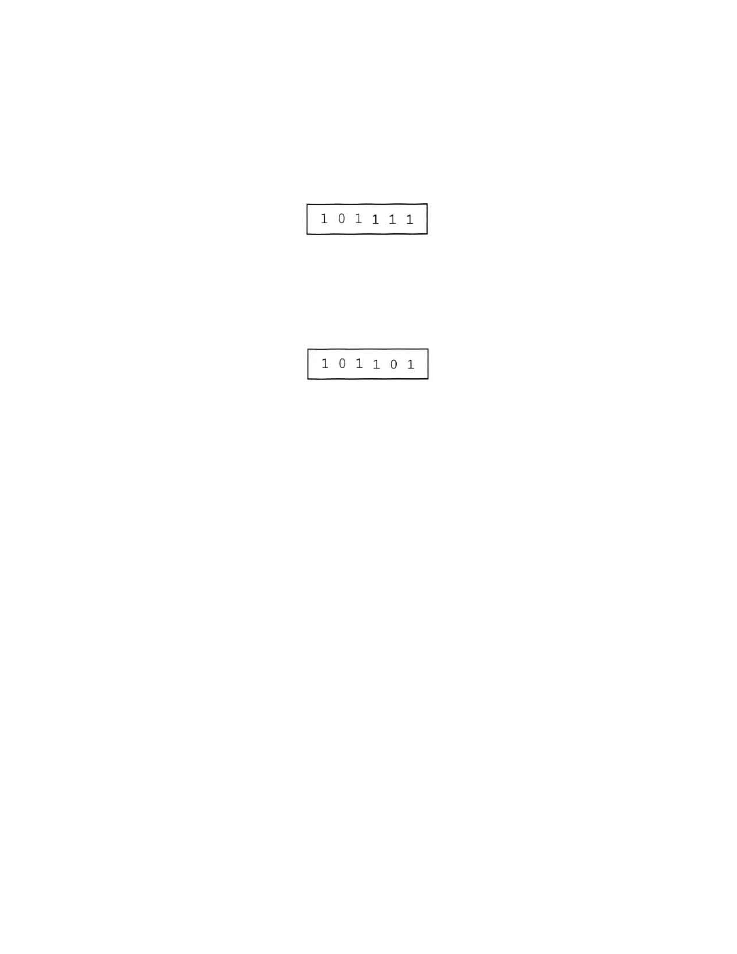
plate. Then, set the DIP switches from left to right. For example - If band A-3 to Channel 13 is
desired, its corresponding code is:
C)
AFC SELECTION - Most off-air TV stations are usually very close to the specified carrier
frequency such that the AFC function need not be used. However, some UHF stations have a
tendency to drift, so it is best to utilize the AFC function. Simply set the AFC switch (fifth switch
from the left) to the down position for automatic frequency control (AFC “ON”). For example - If
AFC is desired on band A-3 to Channel 13, then the set up is:
Off-cable processing should not require AFC, but make sure the proper code sheet (Standard
Channel or HRC) is utilized.
D)
INPUT CONNECTION - After an input channel has been selected (Steps A through C), connect an
antenna or cable source to the RF input terminal. Any VHF, UHF or cable source can be connected
to the RF input connector. For optimum video quality response, the input signal level should have a
minimum of +10dBmV. This unit will function with input signal levels as low as -20dBmV. Any signals
below -20dBmV will be squelched by the internal squelch circuit.
3) DEMODULATOR AGC ADJUSTMENT
A)
The demodulator delayed AGC adjustment is factory set for a +5 to +10dBmV threshold. This setting
provides the best signal-to-noise ratio for low level off-air signals.
B)
For cable operation, where high-level adjacent channel signals may be present, adjacent channel
performance may be improved by lowering the AGC threshold level.
C)
To adjust the delayed AGC threshold level for cable operation:
1.
Connect a cable signal carrying three adjacent channels at a level of +20dBmV maximum to
the RF input connector.
2.
Set the input channel select DIP switches to the channel located in the center carrier frequency
(of the three channels).
3.
Adjust the demodulator delayed AGC control (R54) slightly for the least amount of adjacent
channel interference.