Olson Technology OTR-3550 User Manual
Page 7
025-000156 REV F
Page 7
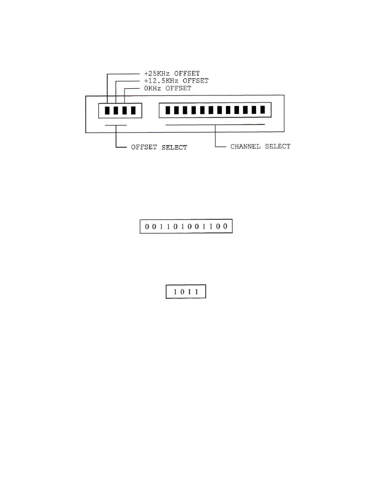
4) OUTPUT CHANNEL SELECTION - MODULATOR
Remove the front panel plate marked “Output Channel Select” to expose the channel select and offset select
DIP switches as shown in Figure 4.
FIGURE 4 - OUTPUT CHANNEL SELECT
A)
CHANNEL SELECTION - Channel selection is accomplished by setting the 12-position DIP
switches to the corresponding channel code. Channel codes can be chosen from Figure #5 or the
code card attached to the “Output Channel Select” cover plate. Then, set the DIP switches from
left to right. For example - If channel 11 is selected, then its corresponding channel code is:
B)
F.C.C. OFFSET SELECTION - Accomplished by setting the 4-position DIP switches to the
corresponding offset code. Offset codes can be chosen from Figure #5 or from the code card
attached to the “Output Channel Select” cover plate. For example if offset code +12.5KHz is
required, the switches would be set as follows:
C)
OUTPUT CONNECTION - The output signal is present at the RF output connector. Also, this unit
provides a -20dB test point for your convenience.
5) RF AND AURAL CARRIER LEVEL ADJUSTMENT
A)
Connect a spectrum analyzer or field strength meter to the RF output connector. Set the video carrier
to the desired level with the RF output level control. This unit is capable of +60dBmV typical output
and can be adjusted downward by 10dB minimum.
B)
Tune the field strength meter to the aural carrier (4.5MHz above the video carrier). Adjust the aural
carrier level to be approximately 15dB below the video carrier.
CAUTION:
Reducing the visual/aural carrier ratio to less than 15 dB can result in high out-of-band
spurious signals in adjacent channels.