ONICON System-10 P1 User Manual
Page 23
11451 Belcher Road South, Largo, FL 33773 • USA • Tel +1 (727) 447-6140 • Fax +1 (727) 442-5699 • [email protected]
System-10-P1 Manual 10/14 - 0656-9 / 18320
Page 23
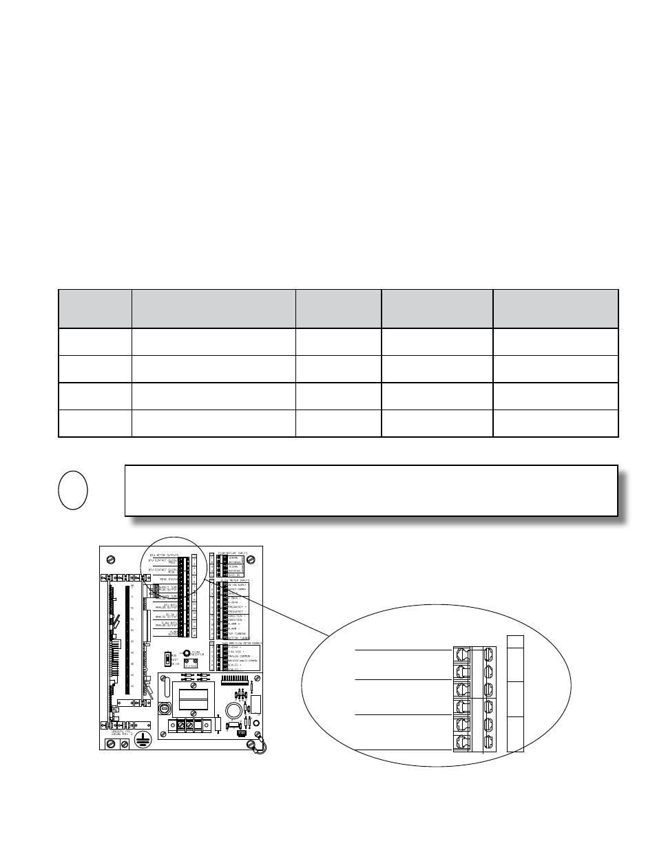
3.3.3 Contact Closure Output For Energy Total(s) And Mode Status
For single mode applications (heating or cooling), the output relay for energy total is
located on the mother board at T1, pins 1 and 2. The value of each “closure” is listed on
the certificate of calibration and is the same as the energy total multiplier displayed on the
LCD (example: each closure = 10,000 BTU’s).
For dual mode applications (two-pipe heat/cool), the energy total for the heating mode
(where supply temp is greater than return temp) is provided at T1, pins 1 and 2. The
energy total in the cooling mode is provided at T1, pins 3 and 4. Mode status is at T1, pins
5 and 6 (open contact = mode 1 operation).
For bi-directional applications, the table below describes the relationship between mode 1
and mode 2 totals and forward and reverse flow for ONICON isertion turbine and inline
electromagnetic flow meters.
Do not exceed 4.5 in-lb (0.5 Nm) of torque when tightening the terminals.
FLOW
METER
MODEL
FLOW DIRECTION
RELATIVE TO
DIRECTION ARROW ON METER
FLOW METER
OUTPUT
CONDITION
SYSTEM-10 MODE
STATUS INDICATOR
(T1 - PINS 5 & 6)
SYSTEM-10 REGISTER
ACCUMULATING
TOTALS
FB-1200
Series
Flow in the direction of arrow
Closed contact
Open contact
Mode 1
FB-1200
Series
Flow reverse from direction arrow
Open contact
Closed contact
Mode 2
F-3000 Series
Flow toward (+) sign
Not energized
(open)
Closed contact
Mode 2
F-3000 Series
Flow toward (-) sign
Energized
(closed)
Open contact
Mode 1
i
IMPORTANT NOTE
This output is generally not utilized on BTU meters that are connected to the FLN, P1 network.
J1
5
G
60HZ
1
J2-1
+15
+24
J2-12
G
G
10
R7
H3
R1
20075-50 REV. A
LED1
T1
D1
D2
VAR1
F1
1/4 AMP
TB1
D4
D3
H1
1
BTU METER OUTPUTS
BTU CONTACT OUTPUT
MODE 1
BTU CONTACT OUTPUT
MODE 2
MODE STATUS
T1
1
2
3
4
5
6
L1 N
Not Used