Example 5 – OWON MSO Series User Manual
Page 103
98
Example 5:
Examine the Phase shift between two related
signals
X-Y mode is a very useful when examining the Phase shift of two related signals.
This example takes you step by step to check out the phase change of the signal after
it passes a specified circuit. Input signal to the circuit and output signal from circuit
are used as sources signals.
1. Set up attenuation coefficient to 10X through Probe menu for both CH1 and CH2.
Switch Probes to 10X. For source signals, CH1 takes in input signal to the circuit
and CH2 takes in output signal from circuit.
2. Press AUTOSET, adjust VOLTS/DIV for both CH1 and CH2 to the same
amplitude level to get an ellipse.
3. Press DISPLAY to activate DISP SET menu, then F3 to select XY mode. Now
the waveform is displayed as Lissajou's curve, adjust VOLTS/DIV and
VERTICAL POSITION to get the best possible display, work out the phase
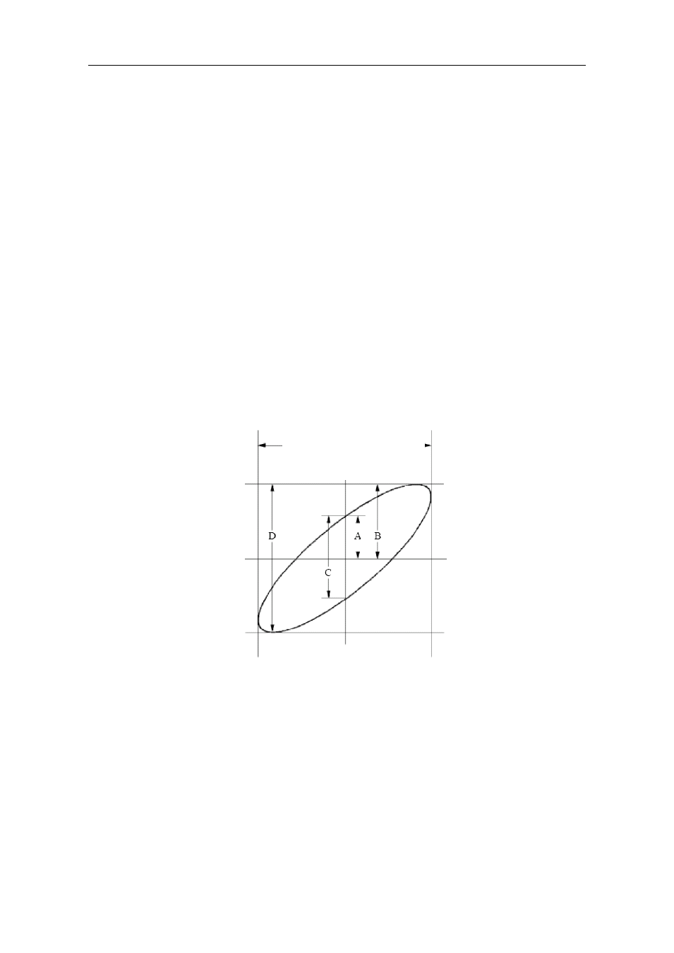
shift as in Fig.6-6.
Fig.6-6 Lissajous Graph
Based on the expression sin =A/B or C/D, where, q is the phase difference angle, and
the definitions of A, B, C, and D are shown as the graph above. As a result, the phase
difference angle can be obtained, namely, q =± arcsin (A/B ) or ± arcsin (C/D). If the
principal axis of the ellipse is in the I and III quadrants, the determined phase
difference angel should be in the I and IV quadrants, that is, in the range of (0-
π /2)
or (3π / 2- 2π). If the principal axis of the ellipse is in the II and IV quadrants, the
determined phase difference angle is in the II and III quadrants, that is, within the
range of (π / 2 - π) or (π- 3π /2).
The signal must be
centered and kept in the
horizontal direction.