Proper techniques for quality repeater audio – Pacific Research Solutions RI-1 User Manual
Page 16
Pacific Research Solutions
RI-1 and PE-1 User Manual
Page 10
SECTION 4
INSTALLATION (RI-1)
If you are installing the PE-1 into the RI-300 chassis, you
can skip to the next section.
This section will cover connecting your RI-1 to your
repeater in detail. To ensure a successful installation, please
follow these few simple steps.
1. Review this section completely and plan you repeater
interface before you start making connections.
2. Review section 6 of this manual for detailed
information on making audio level adjustments.
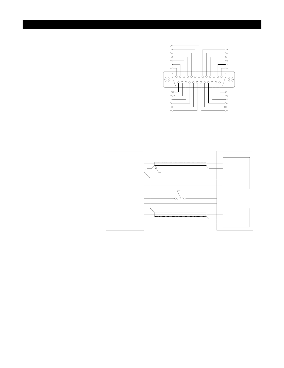
The diagram on the right is an end view of the radio
interface connector on your RI-1. Use the supplied DB-25S
female connector for making all connections to the
controller.
PROPER TECHNIQUES FOR QUALITY REPEATER AUDIO
Obtaining good audio in any repeater
is based on understanding the design
of the equipment. The audio in all
frequency modulation (FM)
transmitters or phase modulation
(PM) transmitters has what is known
as audio pre-emphasis. Pre-emphasis
means that with increasing audio
frequency the amount of the
modulation will increase. The
reverse is performed in all FM
receivers and is called de-emphasis.
The RI-1 was designed to operate
with both emphasized and flat audio
response from the repeater receiver
and transmitter. This means that you
can bypass the de-emphasis and/or
pre-emphasis stage in the radio when
possible. This leaves all of the emphasis filtering in the user’s radio. The RI-1 will interface to emphasis audio when needed.
The RI-1 controller does include a low pass filter that rolls off the very high audio frequency content to prevent adjacent
channel splatter. It is not advisable to drive the microphone input on the transmitters. Most transmitters have significant audio
shaping, compensating for the microphone response and other characteristics.
Besides audio frequency response, you should consider the audio amplitude levels to and from the controller. If the levels to
and from the repeater are small, it may be valuable to use shielded cable. We recommend shielded cables at all times. Use
large signal levels whenever possible. On the other hand, do not let the audio signal get large enough where clipping occurs in
any stage of the controller, the receiver, or the transmitter. See section 6 for more details on adjusting the audio levels in the
controller. Consider and practice the above and you will have repeater audio that you and your repeater users will be proud of.
Audio Input (RX)
Audio-Ground
Digital-Ground
PTT (Open Drain)
Audio Output (TX)
+12V Supply
Radio Data Out
RI-1 Interface Connector
13
12
11
10
9
8
7
6
5
4
3
2
1
14
16
15
18
17
19
24
20 21 22 23
25
5Volts@25mA Out
Radio Data In
Radio Pwr Switch
Radio Pwr Detect
Sypply-Ground
User In 2
User In 1
SLE
SCK
SDA
RS-232 TXD
RS-232 RXD
RS-232 CTS
RS-232 RTS
User Out 1 (Open Drain)
User Out 2 (Open Drain)
TSQ (CTCSS)
NSQ (COS)
Transmitter
Modulator In
Gnd
TX Key (PTT)
+12 Volt Supply Output
Supply Return
Discriminator Out
Gnd
Receiver
REPEATER/RADIO
RX-Audio In (2)
Audio Ground (15)
+12 VDC Power Input (5)
Power Ground (14)
TX-Audio Out (3)
Push To Talk (4)
RI-1 Repeater Controller
Repeater/Radio Connections
SHIELD
1/8 Amp Fuse
TSQ In (7)
TSQ (CTCSS)
NSQ In (6)
NSQ (COS)