Air systems, Calculating compressor size, Calculated required piping – Paslode PF350S PowerFramer 30 Framing Nailer User Manual
Page 8: Pneumatic system maintenance - be certain that
8
AIR SYSTEMS
- Continued
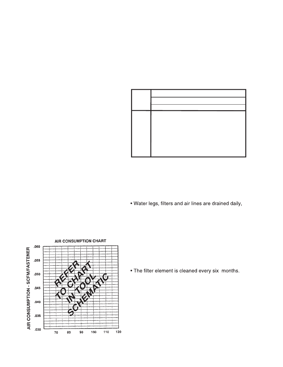
Calculating Compressor Size
Use the air consumption chart in the Tool
Schematic for eaxh tool when calculating the
operating requirements for the tools.
Paslode
tools are designed to operate efficiently
between 80 and 120 psi and should never be
operated at pressure greater than 120 psi.
The air consumption chart will help you find
the correct compressor size for your appli-
cation that will quickly replenish tool air pres-
sure. To use the chart you will need to know
how many tools will be used and approxi-
mately how many fasteners will be driven
each
minute by each tool onthe line.
Number of tools X average fasteners/minute/
tool X 1.2 (safety factor) X air consumption
(scfm) @ pressure* (psi) = scfm required.
We can use the following example:
10 tools X 30 fasteners/minute/tool X 1.2 X
0.051scfm* (@100psi) = 18.36 scfm.
*This number is found in the Air Consumption
Chart
In this example, using the air consumption
chart we find that a compressor providing at
least 19 scfm of air is required. Because in
compressors approximately 1 hp is required to
produce 4 scfm, a compressor of at least 5 hp
is required.
Calculated Required Piping
For example, given a 20 hp electric compressor
supplying approximately 80 cfm of air at 120 psi
and a main supply pipe length of 350 feet, we see
by the table the minimum main pipe inside diam-
eter required for this
application is 1-1/4 inch.
Pneumatic System Maintenance
- Be certain that:
• Pneumatic fittings are tight and do not leak.
and ensure that automatic draining systems are
operating correctly.
• Air lines are cleared to prevent freezing,
especially in winter.
• Lubricator operation is checked regularly and
ensure it has an adequate supply of lubricant.
(Paslode Part No. 403720)
• Only regulated air is being used and that each
regulator is operating properly.
Using the equation:
VOLUME
OF AIR
(CFM)
LENGTH OF RUN (FT.)
NOMINAL PIPE DIAMETER (IN.)
50-200 290-500 500-1000 1000-2500 2500-5000
30-60
60-100
100-200
200-500
500-1000
1 1 1¼ 1½ 1½
1 1¼ 1¼ 2 2
1¼ 1½ 2 2¼ 2½
2 2½ 3 3½ 3½
2½ 3 3½ 4 4½