7 electrical connection, Electrical connection – REMKO RKL 491 DC User Manual
Page 17
Advertising
7
Electrical connection
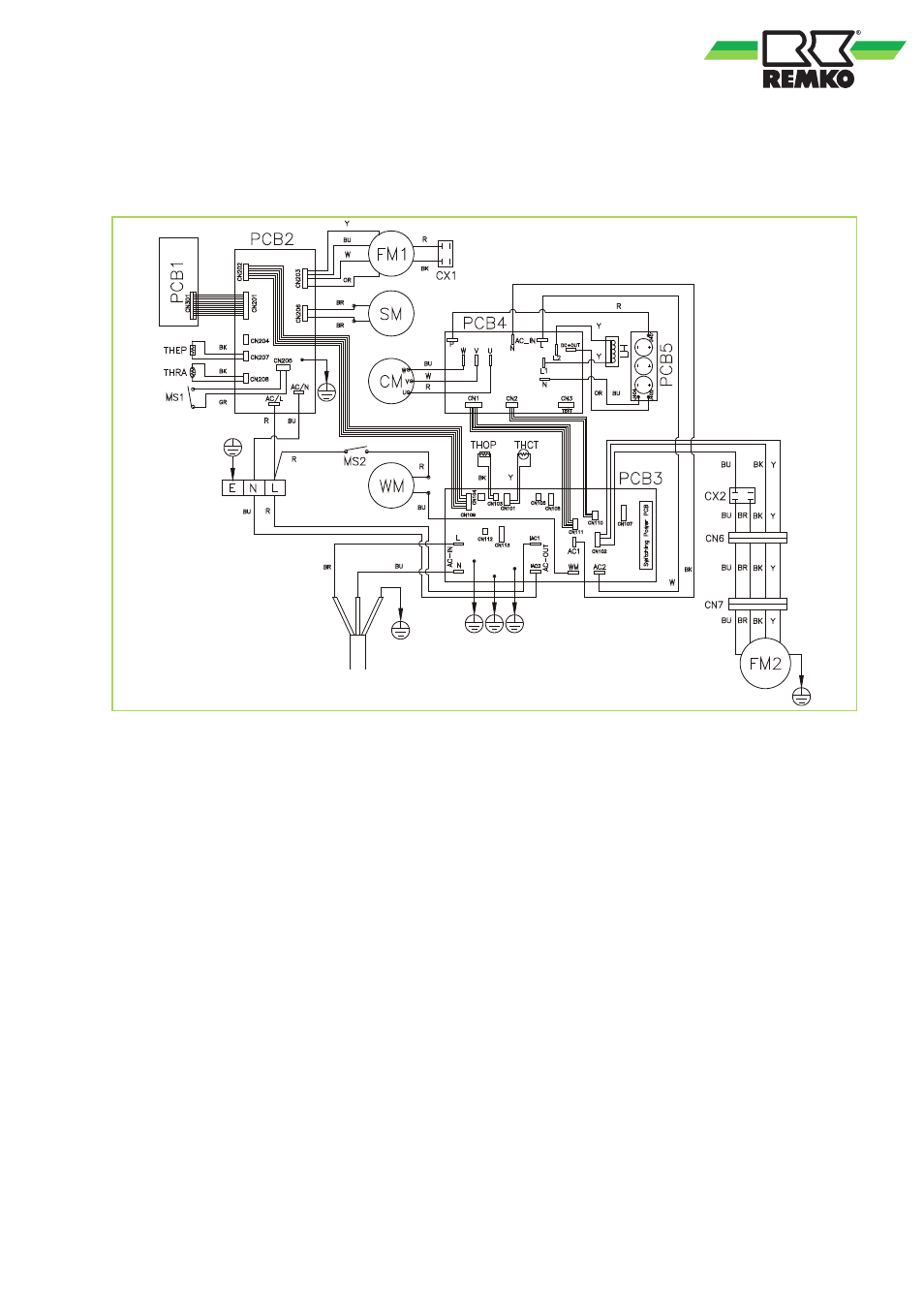
Electrical connection diagram
Fig. 17: Electrical connection diagram
PCB1
Control board
PCB2
Main board
SM
Swing motor
FM1
Vaporiser fan
FM2
Condenser fan
WM
Condensate pump
CM
Compressor
OLP
Compressor excessive temperature protec-
tion
CX1
Condenser, vaporiser fan
CX2
Condenser, condenser fan
CX3
Condenser compressor
RT
Sensor circulating air temperature
CT
Sensor frost protection
MS1
Microswitch alarm (container full)
MS2
Microswitch condensate pump
Colour code:
BK
Black
BR
Brown
BU
Blue
GR
Gray
OR
Orange
R
Red
W
White
Y
Yellow
17
Advertising
This manual is related to the following products: