Wiring diagram – REMKO GTF-5 User Manual
Page 7
Advertising
7
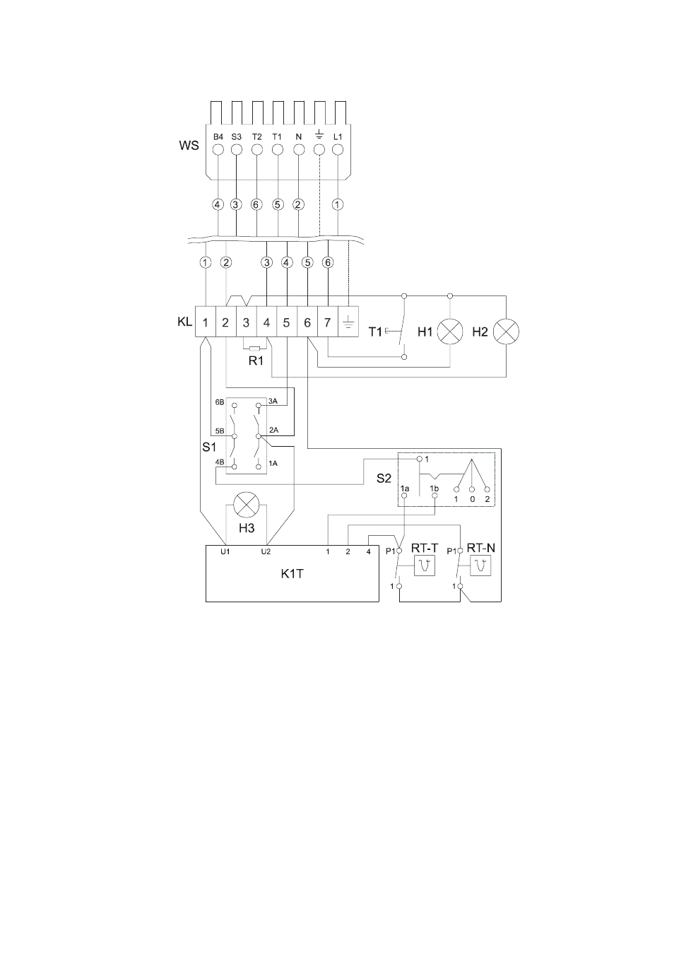
Wiring Diagram
H1 = Control light green
H2 = Control light red
H3 = Power control light green
KL = Terminal strip
R1 = Resistance
RT-N = Night thermostat
RT-T = Day thermostat
S1 = Operating switch
S2 = Mode selector
T1 = Reset button
WS = Plug, 7-pole
Operation/handling which does not comply with these instructions is
prohibited! In cases of non-compliance, we assume no liability and the
guarantee becomes null and void.
Only have the REMKO GTF 5 temperature control installed and
put into operation by authorised personnel in accordance with the
relevant regulations.
G
Plug for heater
Advertising
See also other documents in the category REMKO Radiators:
- PWL H (24 pages)
- CLK 150 (20 pages)
- ELT 2-1 (12 pages)
- CLK 170-RV (24 pages)
- DZH 90-2 (20 pages)
- ELT 18 S V.2 (12 pages)
- ELT 9 (12 pages)
- ELT 9-6 (12 pages)
- EST (8 pages)
- PGM 60 (16 pages)
- PGM 12 (12 pages)
- HTL 400 (20 pages)
- PGT 100 (20 pages)
- ATR-3 (16 pages)
- ATR-4 (16 pages)
- SLV11-88-2 (16 pages)
- PWW Series (36 pages)
- VRS Series (36 pages)
- GSG-4 (8 pages)
- GPM 75 (44 pages)
- ATR-2 (8 pages)
- ASF 100 (16 pages)
- ETF 460 (20 pages)
- ETF 320 (20 pages)
- ETF 550 (20 pages)
- WKL 30 INOX (24 pages)
- SLN 80 (20 pages)
- RBW 300 PV-S (48 pages)
- HTS 260 CAMURA (76 pages)
- WKF 180 Duo S-line (64 pages)
- WKF-compact S-Line (96 pages)
- AMT 15 (16 pages)
- AMT 25 (16 pages)
- ETF 220 (16 pages)
- TX 3000 (8 pages)
- PG 50 (16 pages)
- TX 9000 (8 pages)
- CLK 20 (20 pages)
- AT 25 (16 pages)
- DZ 18 HD (16 pages)
- HTK 160 (20 pages)
- PG 12E (16 pages)
- PWL (24 pages)
- PWW 5000 (12 pages)