Wiring diagram – REMKO ATR-1 User Manual
Page 7
Advertising
7
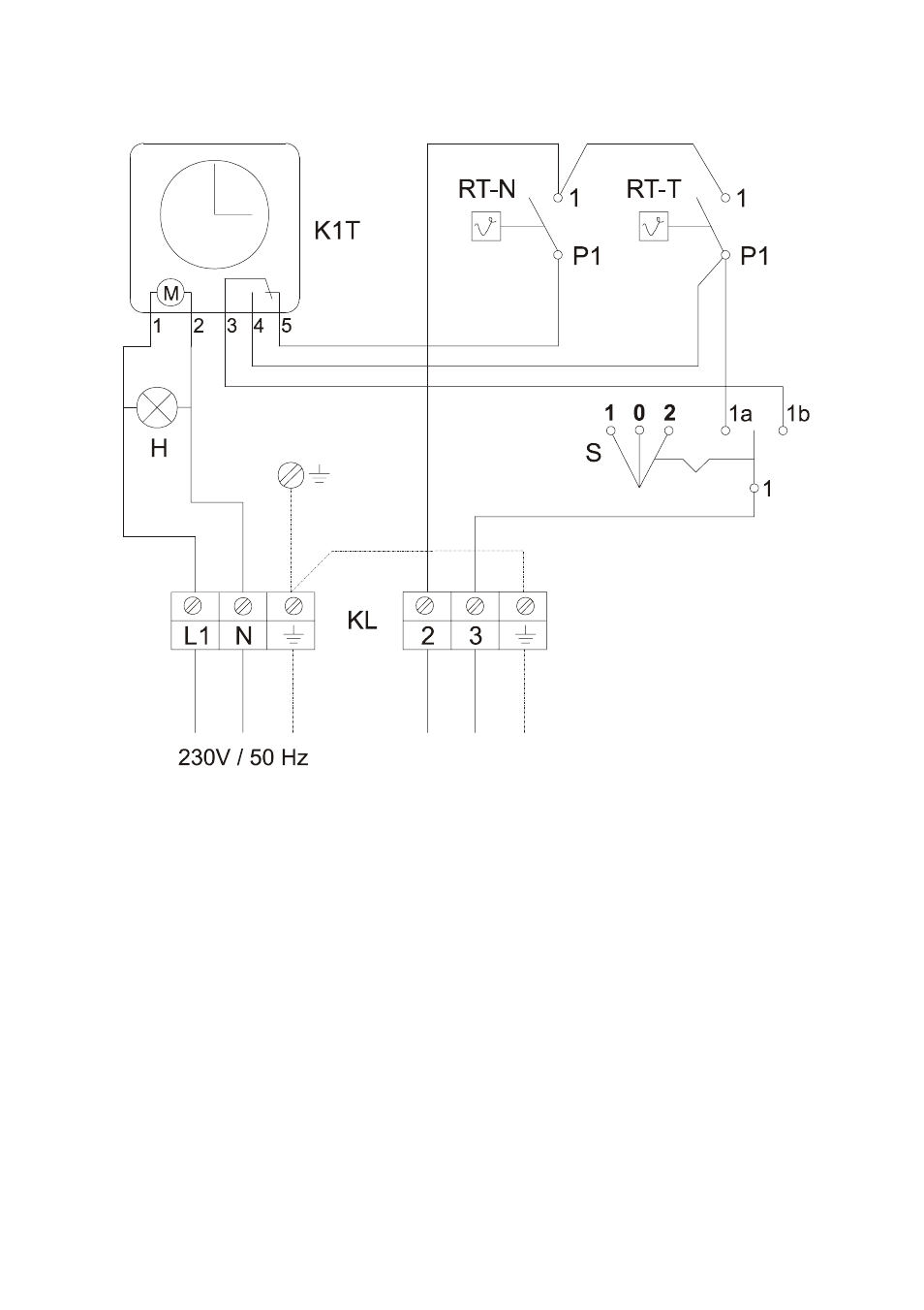
Wiring diagram
H = Power control light (green)
K1T = Timer
KL = Terminal strip
RT-N = Night thermostat
RT-T = Day thermostat
S = Mode selector (1 = Day, 0 = Off, 2 = Timer)
Operation/handling which does not comply with these instructions is
prohibited! In cases of non-compliance, we assume no liability and the
guarantee becomes null and void.
Only have the REMKO ATR-1 temperature control installed and
put into operation by authorised personnel in accordance with the
relevant regulations.
G
Thermostat connection
Advertising
This manual is related to the following products: