Remko cmf - duo, Terminal block/legend – REMKO CMF 320 Duo User Manual
Page 44
REMKO CMF - DUO
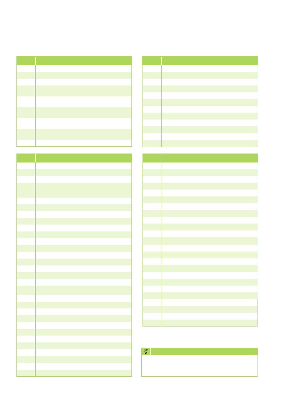
Terminal block/legend
Termi-
nal
Connection layout (low-voltage sensor)
X3.
Earth
X3.1
CAN-Bus +
X3.2
CAN-Bus -
X3.3
CAN-Bus L
X3.4
CAN-Bus H
X3.5
eBus - (nominal output in % above 0-10 V -signal)
X3.6
eBus + (nominal output in % above 0-10 V -signal)
X3.7
F17 Return sensor (cooling-control sensor)
X3.8
F15 sensor (option: flow-volume regulator)
X3.9
F14 Solar-collector sensor (pt 1000)
X3.10
F13 Solid-fuel-boiler sensor F13 (pt 1000)
X3.11
F12 Lower buffer storage
(reference sensor, solar or solid-fuel boiler)
X3.12
F11 Inlet sensor, heat pump or heating-circuit 1
X3.13
F9 External sensor
X3.14
F8 Collector sensor, common inlet (heating-control sensor)
X3.15
F6 Warm-water-storage sensor
X3.16
F5 Inlet sensor, heating-circuit 2 (mixing circuit)
X3.17
F3 (not connected)
X3.18
F2 (not connected)
X3.19
F1 (not connected)
X3.20
Liquid-temperature sensor, outdoor unit A
X3.21
Undercooling temperature, outdoor unit A
X3.22
Liquid-temperature sensor, outdoor unit B
X3.23
Undercooling temperature, outdoor unit B
The connection terminals X1.4 through x1.9, as
well as X2.15 and X2.18 are available only when
the electric booster heater is installed.
NOTE
Termi-
nal
Connection layout (outputs)
X2.1
Control cable, outdoor- and indoor module - S1
X2.2
Control cable, outdoor- and indoor module - S2
X2.3
Control cable, outdoor- and indoor module - S3
X2.4
Enable 2. Heat generator (common contact,
optionally potential free or 230 V feed over the
bridge at X2.19)
X2.5
Enable 2. Heat source (open)
X2.6
Enable 2. Heat source (closed)
X.2.7
Switching valve 2. Heat generator - OPEN
X2.8
Switching valve 2. Heat generator - N
X2.9
Switching valve 2. Heat generator - OFF
X2.10
Mixer, heating circuit 2 - OPEN
X211
Mixer, heating circuit 2 - N
X2.12
Mixer, heating circuit 2 - CLOSED
X2.13
Power plant enable/disable
X2.14
Power plant enable/disable
X2.15
Contactor K6-A1/L‘, 6 kW elec. booster heater
X2.16
Flow monitor
X2.17
Flow monitor
X2.18
Contactor K6 and K8-A2/N1.2, elec. booster
heater
X2.19
Live phase - L'
X2.20
Live phase - L'
X2.21
Live phase - L'
X2.22
Circulation pump, heating circuit 1 - L
X2.23
Circulation pump, heating circuit 1 - N
X2.24
Circulation pump, heating circuit 1 - PE
X2.25
Circulation pump, heating circuit 2 - L
X2.26
Circulation pump, heating circuit 2 - N
X2.27
Circulation pump, heating circuit 2 - PE
X2.28
Switching valve, warm water L" - black
X2.29
Switching valve, warm water N - grey
X2.30
PE
Termi-
nal
Connection layout (supply)
X1.1
Power supply, indoor module - L
X1.2
Power supply, indoor module - N
X1.3
Power supply, indoor module - PE
X1.4
Power supply, E-heater - L1
(optional for CMF Series).
X1.5
Power supply, E-heater - N
(optional for CMF Series).
X1.6
Power supply, E-heater - PE
(optional for CMF Series).
X1.7
Power supply, E-heater - L2
(optional for CMF Series).
X1.8
Power supply, E-heater - L3
(optional for CMF Series).
X1.9
PE
Termi-
nal
Connection layout (outputs) continuation
X2.31
Switching valve, cooling L" - black
X2.32
Switching valve, cooling N - grey
X2.33
PE
X2.34
Circulation pump, cooling - L
X2.35
Circulation pump, cooling - N
X2.36
Circulation pump - PE
X2.37
Circulation- or solar pump - L
X2.38
Circulation- or solar pump - N
X2.39
Circulation- or solar pump - PE
X2.40
Charge pump, indoor module - L
X2.41
Charge pump, indoor module - N
X2.42
Charge pump, indoor module - PE
44