Rms 5533 back panel, Power, Sdi loop out – RGBLink RMS 5533 User Manual
Page 24: Sdi input, Cvbs input, 5:cvbs loop out, Panel instruction
Advertising
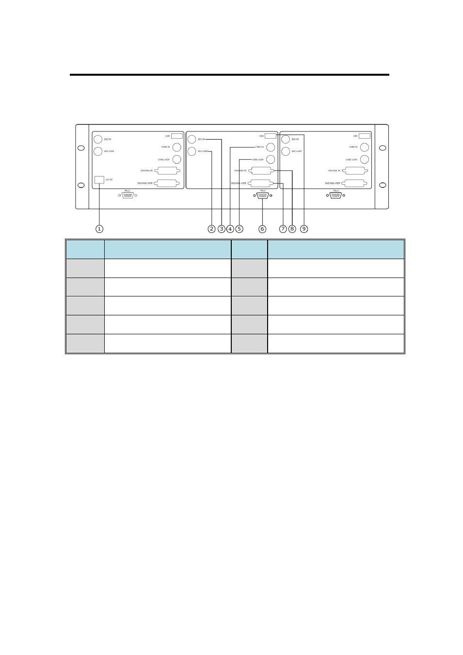
2. Panel Instruction
RMS 5533 Back Panel
RMS 5533 User Manual 24
Back view:
NO.
INTERFACE
NO.
INTERFACE
1
Power
6
TALLY Control Port
2
SDI Loop Out
7
DVI/VGA Loop Out
3
SDI Input
8
DVI/VGA Input
4
CVBS Input
9
USB Port
5
CVBS Loop Out
1: Power
DC 12V IN: Connect with DC12V power adapter. Power polarity is:
negative inside and cathode outside.
2: SDI Loop Out
SDI LOOP: Standard BNC connector.
3: SDI Input
SDI IN: Standard BNC Connector.
4: CVBS Input
CVBS IN: Composite video input (BNC connector).
5:CVBS Loop Out
CVBS LOOP: Composite video loop out (BNC connector, it is valid only
when switch the signal to AV channel).
Advertising