Electrical sequence, Slc300, Initial start up – Scotsman SLC300 User Manual
Page 13
Initial Start Up
Note: If the first batch of cubes are not all uniform
discs, some ice machine cleaner should be added
to the reservoir.
1. After ice has been harvested, but before new
cubes begin to form, switch the ICE/OFF/WASH
switch to WASH.
2. Add 4 oz. of ice machine cleaner to the
reservoir. Allow unit to operate that way for 10
minutes.
3. Switch ICE/OFF/WASH switch to OFF
4. Shut the water supply off.
5. Remove the splash guard, and drain the
reservoir by removing the drain elbow.
7. Replace all parts, turn on the water and move
ICE/OFF/WASH switch to ICE. The next batch of
ice should be uniform.
13. Check harvest. The machine will have to
harvest all of the cubes before it goes back into the
freeze cycle.
14. Check operation of the bin control circuit by
holding ice on the bin control tube in the bin.
If the ice maker does not stop within 1 minute,
while keeping ice on the thermostat, rotate the bin
thermostat shaft counter clockwise until the ice
maker does stop. Remove the ice from the
capillary tube; the ice maker should restart within 2
minutes. If it does not, rotate the adjusting shaft
clockwise until the machines starts.
15. Replace all the panels. The ice machine is now
ready for automatic operation.
Electrical Sequence:
This describes the sequence through a complete
cycle.
Freeze Cycle:
During the first part of the freeze cycle, the ice
machine compressor, fan motor if air cooled, and
water pump are operating.
Assume the bin thermostat is closed.
The ice size thermostat contact 2-3 are closed,
connecting power to:
••
The fan motor (thru relay)
••
The pump motor (thru relay and ice/off/wash
switch.
The Harvest Termination Thermostat is closed, but
there is no power thru it.
The ice size thermostat heater is on.
Harvest:
In the harvest cycle, the compressor is operating,
and the hot gas valve is energized. The water
pump is off, and air cooled models switch the fan
off.
The bin thermostat is still closed.
When the ice near the ice size thermostat sensing
tube grows large enough to force water over the
sensing tube, that tube looses heat, and at 38
o
F.
contacts 2-3 open and 2-1 close.
This removes power from the water pump and fan
and connects power to the relay coil. When the
relay coil has power, it connects power to the:
••
Hot gas valve coil
The harvest termination switch is closed, and
power flows thru it to the relay coil. This keeps the
relay energized, even when the ice size thermostat
switches contact position as a result of ice falling
away from the sensing tube.
The ice size thermostat heater is on.
The unit stays in the harvest cycle until the
thermodisc on the suction line warms up to 55
o
F.,
At that time the harvest cycle is terminated, and
the unit will go back into the freeze cycle.
Whenever there is ice on the bin thermostat, it
opens and stops the ice making process.
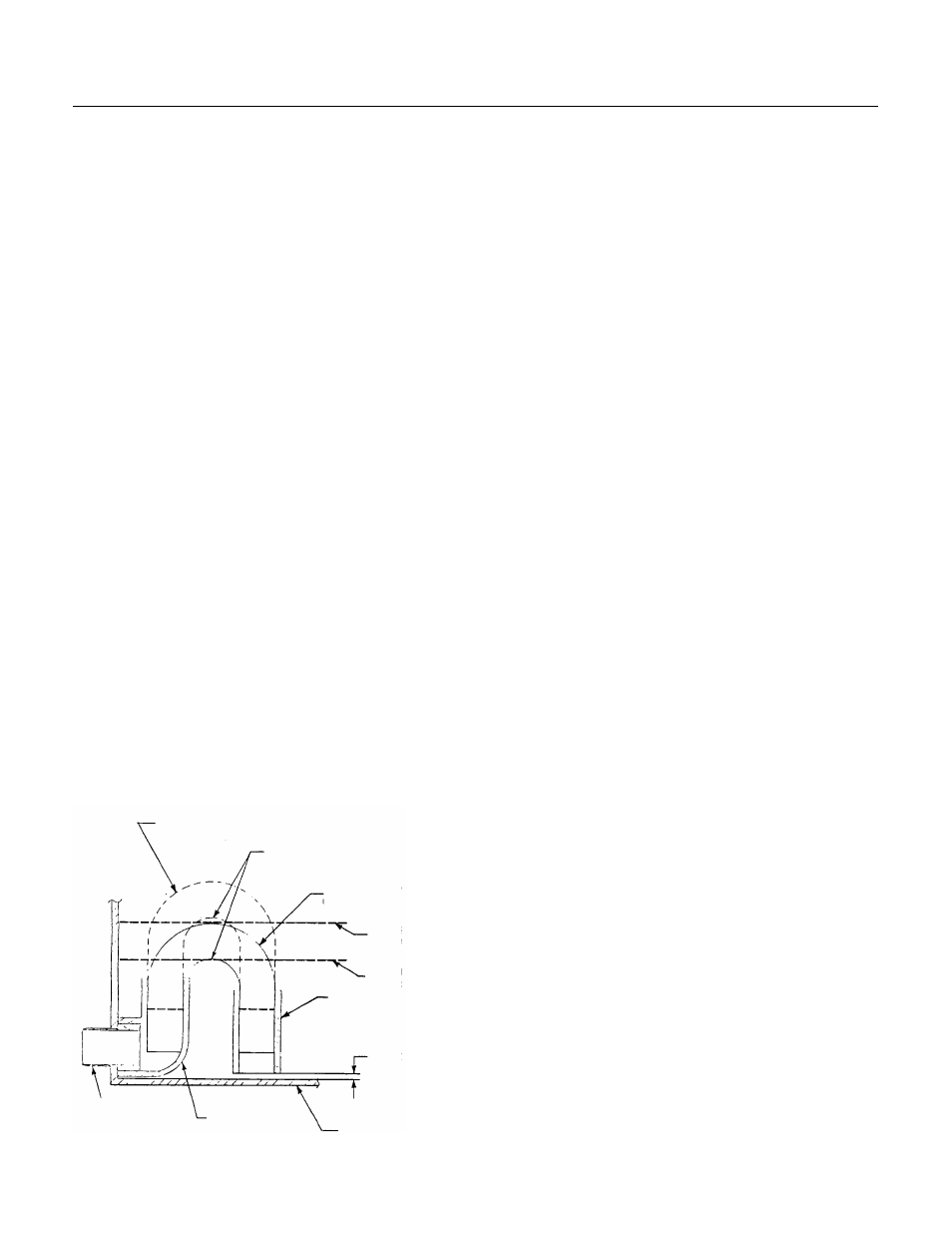
Siphon Tube Schematic
U-Tube Adjusted
Here = No Purge
Siphon Breaker Hole
U-Tube Here =
Maximum Purge
Water Level
At Harvest
Water Level With
Pump ON
Water Inlet
1/8 - 1/4
Bottom of
Reservoir
Elbow
Drain Outlet
SLC300
November 1994
Page 13