Seaward PV150 Quick start User Manual
Installation pv150, Quick reference guide, Null
www.seawardsolar.com
Otras funciones
Funciones de memoria
Captura todas las mediciones presentes en el visor.
Recupera las mediciones en el visor.
En el modo recuperar, se desplaza hacia atrás por la memoria
Despeja todos los resultados de la memoria
Límites de aislamiento
Viso
Resistencia de aislamiento mínima
250V 0.5M
Ω
500V 1.0M
Ω
1000V 1.0M
Ω
Campos de medición
Function Range
Rpe 0
Ω - 199Ω/30V - 440V
Vo/c 5V
-
1000V
Is/c
0.5A - 15A
Insulation 0.05M
Ω - 199MΩ
I ac/dc
0.1A - 40A
Mensajes de advertencia
Mensaje de error
Solución
El fusible interno se ha fundido. Consulte la sección 8.5 en
las instrucciones de funcionamiento para los detalles sobre
el cambio de fusible.
La electrónica interna del PV100 ha alcanzado la temperatura
máxima segura. Esto puede ocurrir después de repetidas
mediciones de intensidades de cortocircuito elevadas.
Deje enfriar la unidad antes de volver a usarla.
La intensidad de cortocircuito en CC ha sobrepasado el valor
nominal máximo de 10A. Se ha abortado la secuencia de
medición.
Read the operating instructions before using this instrument. This equipment
should only be used by suitably trained personnel. The PV150 is intended for
use in a dry environment only. The red and black 4mm test terminals may be
used to make measurements on circuits rated up to CATIII 300V AC/DC with
reference to earth/ground. Do not connect the PV150 to voltages which may
exceed this rating. PV test terminals maximum rating: 1000V DC open circuit
voltage, 15A short circuit current. Do not exceed this rating. The DC supply
must be isolated from earth/ground during testing. Check the PV150 and all
associated cables and leads before operating the equipment. Do not use if
there are signs of damage. Only use the test leads supplied with the PV150. Do
not leave the PV150 permanently connected to a PV installation. Always
disconnect immediately after use. High voltages are present at the probe tips
during insulation resistance measurement. Always hold the test probes behind
the barriers. Do not touch any exposed metal parts of the PV installation
during testing. Always ensure that the circuit under test is electrically isolated
before attempting a protective earth/ground resistance measurement.
Important Information
Installation PV150
Quick reference guide
Test lead resistance null
Connect test leads to red and black 4mm sockets on the PV150.
Hold the test probe tips together or connect together using the supplied alligator
clips.
Press and hold the null key until the unit beeps and NULL icon appears on LCD.
Null value is stored when unit is switched off.
To disable, press null key until icon is removed from LCD.
Note: Maximum test lead resistance null = 10Ω
R
PE
V
SO
Auto
NULL
1
2
3
4
5
R
PE
V
SO
Auto
NULL
Protective earth/ground resistance
Connect the test leads a shown.
To make a 2s measurement, press and release the Rpe key.
To make a continuous measurement, press and hold the Rpe key for a few
seconds until the lock icon appears on the LCD.
Press the Rpe key to terminate the continuous
measurement mode.
1
2
3
4
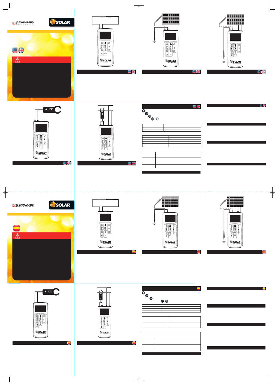
Auto Test (V0/c IS/c & insulation resistance)
Connect the PV150 to the PV module as shown, using the
PV test lead adaptors.
Vo/c is automatically displayed.
If the voltage polarity is incorrect the reversed polarity icon will appear on the
LCD. The auto test sequence is inhibited if the polarity is reversed.
Use the Viso button to select 250V, 500V or 1000V insulation
test voltage.
Press the Auto button to automatically measure Short Circuit Current and
Insulation Resistance.
Note: The red test probe is required for the insulation resistance measurement
1
2
3
4
5
R
PE
V
SO
Auto
NULL
R
PE
V
SO
Auto
NULL
ZERO
40A
AC & DC Current Measurement
Disconnect all cables from the PV150 test inputs.
Connect the current clamp to the red & black 4mm inputs.
Move the current clamp switch to the 40A position.
Press and hold the zero button for 2s on the current clamp.
Press the Auto button. The clamp icon will appear on the LCD.
The measured current is shown on the LCD.
1
2
3
4
5
6
DC Power Measurement
Connect the current clamp to 4mm inputs.
Press the Viso button until the clamp icon appears on the LCD.
Move the current clamp switch to the 40A position.
Press and hold the zero button for a few seconds.
Press the clamp around the DC cable of the solar installation.
DC current is shown on the LCD next to the clamp icon.
Connect the PV voltage to the PV inputs. ‘T’ or ‘Y’ test adaptors are required
if the DC power is to be measured while the PV system is operational.
The DC voltage, current and power will be displayed.
RPE
VSO
Auto
NULL
ZERO
40A
1
2
3
4
5
6
7
8
Other Functionality
Memory Functions
Capture all measurements currently on the LCD.
Recall measurements on the LCD.
In recall mode, scroll back memory.
Clear all results from memory.
Insulation Limits
Viso
Minimum insulation resistance
250V 0.5M
Ω
500V 1.0M
Ω
1000V 1.0M
Ω
Measuring Ranges
Function Range
Rpe 0
Ω - 199Ω/30V - 440V
Vo/c
5V - 1000V
Is/c 0.5A
-
15A
Insulation 0.05M
Ω - 199MΩ
I ac/dc
0.1A - 40A
Warning Messages
Error Message
Remedy
The internal fuse has blown. Refer to section 8.5 in the operating
instructions for details on how to replace the fuse.
The electronics within the PV100 have reached the maximum
safe temperature. This can occur after repeated short circuit
current measurements at high current levels. Allow the unit to
cool down before further use.
The DC short circuit current has exceeded the maximum rated
value of 10A. The measurement sequence has been aborted.
FUSE
HOT
H,SC
+
Downloading to PC
1
Connect the PV150 to PC using the USB cable.
2
(This will create a COM port on the PC).
3
Run the Seaward Solar Datalogger application on the PC.
4
Select the correct COM port. Use the Help menu – Trouble
shooting guide, to help find the correct COM port.
5
Click the Download button.
6
Press and hold the Recall key on the PV150.
Pairing with Survey 200R
1
Make sure there are no other units operating nearby.
2
Turn off both the PV150 and Survey 200R unit.
3
Press and hold the Survey 200R ON/OFF keys, keep both keys pressed.
4
Press and hold the PV150 Rpe and Auto keys, keep both buttons pressed.
5
When the PV150 has successfully paired, it will beep and display the
serial number of the Survey 200R.
6
The top line of the PV150 LCD will show the W/m
2
icon.
Un-pairing from Survey 200R
1
Make sure there are no other units operating nearby.
2
Turn the PV150 off.
3
Press and hold the Rpe and Auto keys on the PV150, keep both
buttons pressed. Keep both buttons pressed for about 10 seconds.
4
The PV150 will then beep and clear its screen. The unit is no
longer paired with a Survey 200R.
5
The top line of the LCD will display Rpe ohms.
Solarlink
1
Pair the PV150 and Survey 200R
2
To enable/disable Solarlink, press and hold the Survey 200R
temperature key, then momentarily press the OK key.
3
When Solarlink is active there is a flashing icon above the
temperature key.
4
If the Survey 200R is within range, the PV150 will indicate the
measured irradiance.
5
If the Survey 200R is not within range, or the measured value is outside
the measuring range the PV150 irradiance value will be replaced with “- - - -”.
Changing Auto Shutdown time
1
Turn the PV150 unit off.
2
Press and hold the NULL key, then press both the ON/OFF keys together.
Keep holding the NULL key.
3
The display will show “OFF” on line 1, and the turnoff time on line 2
(in minutes).
4
Keep holding the NULL key and press the Viso key. Each press of the
Viso key will increment the turnoff time.
5
Increment beyond 10 to set the time back to 1 minute.
Prueba de resistencia nula de los conductores
Conecte los conductores de prueba a las tomas roja y negra
de 4 mm en el PV150.
Mantenga unidas las puntas de las sondas de prueba o conéctelas
con las pinzas cocodrilo suministradas.
Mantenga pulsada la tecla ‘null’ hasta que aparezca en el visor
el icono NULL.
El valor del cero queda almacenado cuando la unidad se apaga.
Para desactivarlo, pulse la tecla ‘null’ hasta que el icono desaparezca del visor.
Nota: Valor máximo de la prueba de resistencia nula de los
conductores = 10Ω
R
PE
V
SO
Auto
NULL
1
2
3
4
5
R
PE
VSO
Auto
NULL
Resistencia de protección a tierra
Conecte los conductores de prueba tal como se indica.
Para hacer una medición de 2 seg., pulse y suelte la tecla Rpe.
Para hacer una medición continua, mantenga pulsada la tecla Rpe durante
algunos segundos hasta que aparezca en el visor el icono de bloqueo.
Pulse la tecla Rpe para terminar el modo de medición continua.
1
2
3
4
R
PE
VSO
Auto
NULL
Auto Test (V0/c IS/c y resistencia de aislamiento)
Conecte el PV100 al módulo PV tal como se indica, usando los adaptadores
para los conductores de la prueba PV.
Se exhibe automáticamente Vo/c.
Si la polaridad es errónea, aparecerá en el visor el icono de polaridad invertida.
El ciclo de ‘auto test’ se inhibe si la polaridad está invertida.
Utilice la función Viso para seleccionar la tensión de prueba de la resistencia de
aislamiento entre 250, 500 o 1000 Voltios.
Pulse el botón ‘Auto’ para medir automáticamente la intensidad de cortocircuito
y la resistencia de aislamiento.
Nota: Se necesita la sonda de prueba roja para medir la resistencia
de aislamiento.
1
2
3
4
5
Lea las instrucciones de funcionamiento antes de usar este instrumento.
Este equipo solo debe usarlo personal adecuadamente formado.
El PV150 está destinado exclusivamente al uso en ambientes secos.
Los terminales de prueba rojo y negro pueden usarse para efectuar
mediciones en circuitos clasificados hasta CAT III: 300V respecto a tierra en
CA/CC No conecte el PV150 a tensiones que sobrepasen este valor nominal.
Valor nominal máximo de los terminales de prueba del PV: 1000 V CC en
circuito abierto, 15A intensidad de cortocircuito. No sobrepase estos valores
nominales. La alimentación de CC debe estar aislada de tierra durante la
prueba.
Compruebe el PV150 y todos sus cables y conductores antes de usar el
equipo. No lo use si presenta signos de daño.
Use solo los conductores de prueba suministrados con el PV150.
No deje el PV150 conectado permanentemente a una instalación PV.
Desconéctelo siempre inmediatamente después de usarlo.
Hay tensiones elevadas en las puntas de las sondas durante la medición de
resistencias de aislamiento. Mantenga siempre las sondas de prueba detrás
de las protecciones.
No toque ninguna parte metálica descubierta de la instalación PV durante la
prueba.
Asegúrese siempre de que el circuito en prueba esté aislado eléctricamente
antes de intentar una medición de la resistencia de protección a tierra.
Información importante
Installation PV150
Guía de consulta rápida
R
PE
VSO
Auto
NULL
ZERO
40A
Medición de intensidades en CA y CC
Desconecte todos los cables de las entradas de prueba del PV150.
Conecte la pinza de intensidad a las entradas de 4 mm roja y negra.
Mueva el conmutador de la pinza de intensidad a la posición 40 A.
Mantenga pulsado durante 2 segundos el botón ‘cero’ de la pinza de
intensidad.
Pulse el botón ‘Auto’. El icono de la pinza aparecerá en el visor.
La intensidad medida se muestra en el visor.
1
2
3
4
5
6
Medición de potencia en CC
Conecte la pinza de intensidad a las entradas de 4 mm.
Pulse el botón Viso hasta que aparezca en el visor el icono de la pinza.
Mueva el conmutador de la pinza de intensidad a la posición 40 A.
Mantenga pulsado durante algunos segundos el botón de puesta a cero de la
pinza.
Coloque la pinza alrededor del cable de CC de la instalación solar.
La intensidad en CC se muestra en el visor junto al icono de la pinza.
Conecte la tensión PV a las entradas PV. Se necesitarán adaptadores de prueba
‘T’ o ‘Y’ si hay que medir la potencia en CC mientras el sistema PV está en
funcionamiento.
Se visualizarán la tensión, la intensidad y la potencia en CC.
R
PE
V
SO
Auto
NULL
ZERO
40A
1
2
3
4
5
6
7
8
FUSE
HOT
H,SC
+
Descarga al PC
1
Conecte el PV150 al PC usando el cable USB.
2
(Esto creará un puerto COM en el PC)
3
Ejecute la aplicación Seaward Solar Datalogger en el PC.
4
Seleccione el puerto COM correcto.
5
(Use el menú de ayuda – guía para resolución de problemas,
para ayudarle a encontrar el puerto COM correcto).
Haga clic en el botón Descargar.
6
Mantenga pulsado el botón Recuperar en el PV150.
Acoplamiento con el Survey 200R
1
Asegúrese que no haya otras unidades funcionando en las proximidades.
2
Apague ambas unidades, el PV150 y el Survey 200R.
3
En el Survey 200R, pulse y mantenga pulsadas las teclas ON y OFF.
4
En el PV150, pulse y mantenga pulsadas las teclas Rpe y Auto.
5
Cuando el PV150 se ha acoplado con éxito, sonará un pitido y se
visualizará el número de serie del Survey 200R.
6
La línea superior del visor del PV150 mostrará el icono de w/m
2
.
Desacoplamiento del Survey 200R
1
Asegúrese que no haya otras unidades funcionando en las proximidades.
2
Apague la unidad PV150.
3
En el PV150, pulse y mantenga pulsadas las teclas Rpe y Auto.
Mantenga ambos botones apretados durante unos 10 segundos.
4
El PV150 emitirá un pitido y la pantalla se borrará. La unidad ha
dejado de estar acoplada al Survey 200R.
5
La línea superior del visor indicara Rpe ohmios.
Solarlink
1
Acople el PV150 y el Survey 200R.
2
Para activar/desactivar el Solarlink, pulse y mantenga apretada la tecla
de temperatura del Survey 200R y pulse un momento la tecla OK.
3
Cuando el Solarlink está activo, hay un icono centelleando encima
de la tecla de temperatura.
4
Si el Survey 200R está dentro del alcance, el PV150 indicará
la irradiancia medida.
5
Si el Survey 200R no está dentro del alcance, o si el valor medido
está fuera del campo de medición, el valor de la irradiancia en el PV150
estará sustituido por “- - - -“.
Cambio del tiempo de auto-apagado
1
Apague la unidad PV150.
2
Pulse y mantenga pulsada la tecla NULL y pulse simultáneamente
las teclas ON y OFF. Siga pulsando la tecla NULL.
3
El visor mostrará “OFF” en la línea 1 y el tiempo de apagado
(en minutos) en la línea 2.
4
Mantenga pulsada la tecla NULL y pulse la tecla Viso. Cada pulsación
de la tecla Viso incrementará el tiempo de apagado.
5
Aumente más allá de 10 para volver a 1 minuto.
www.seawardsolar.com
Seaward Solar, Bracken Hill, South West Industrial Estate,
Peterlee, County Durham, SR8 2SW United Kingdom
Tel: +44 (0) 191 586 3511
Fax: +44 (0) 191 586 0227
Email: [email protected]
Web: www.seawardsolar.com
✁
4135_quickstartlayout:4135_QuickStart_Layout 19/4/12 14:35 Page 1