Sloan ELS-63000 Installaton User Manual
Page 3
PRIOR TO INSTALLATION
TOOLS REQUIRED FOR INSTALLATION
SINK LOCATION
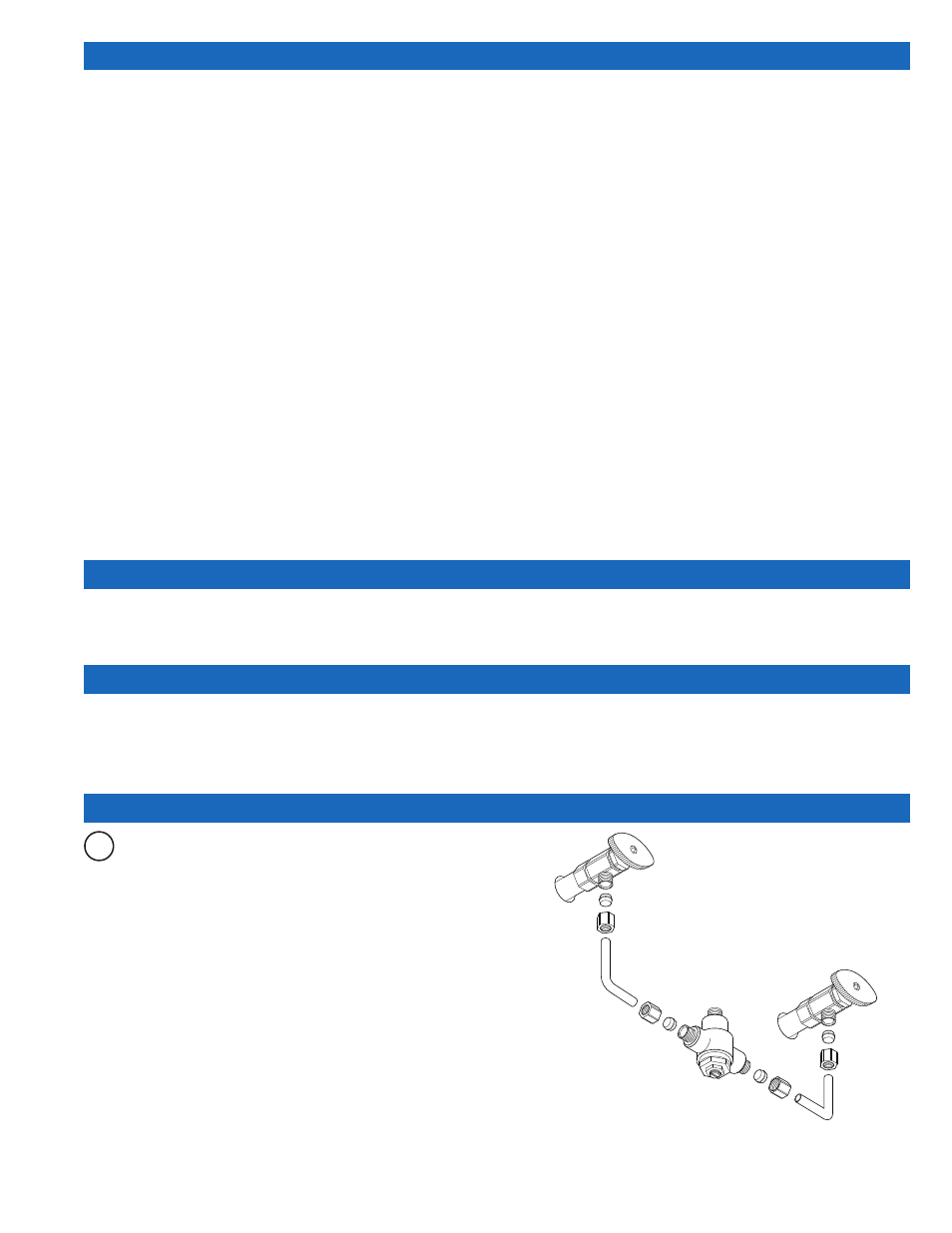
1 – INSTALL THERMOSTATIC MIXING VALVE
Prior to installing the Sloan Optima ELS-60000/ELS-70000 Series
Lavatory System, install the items listed below. Also, refer to the
appropriate rough-in diagram on Page 2 and 3.
• Electrical receptacle(s) – 120 VAC, 2 amp service for plug-in faucets
and soap dispensers. The ELS-73000-xx-MSD 3-station sink with
hardwire soap dispensers in conjunction with hardwire faucets
require TWO electrical outlets (see rough-in on Page 2), all others
require ONE.
• Hot and cold water supply lines or tempered water supply line (If
there is no tempered water supply, install thermostatic mixing valve
between hot and cold water supply)
• Drain lines
IMPORTANT:
•
ADEQUATE STRUCTURAL SUPPORT IN OR BEHIND THE
WALL IS REQUIRED. REFER TO THE APPROPRIATE
ROUGH-IN DIAGRAM ON PAGE 2 FOR DRY WEIGHT OF
SINK. STRUCTURAL SUPPORT MUST HAVE A MINIMUM
PULLOUT RATING OF 1000 POUNDS (450 Kg) FOR EACH
FASTENER.
• ALL PLUMBING SHOULD BE INSTALLED IN
ACCORDANCE WITH APPLICABLE CODES AND
REGULATIONS.
•
BEFORE CONNECTING SUPPLY LINES TO SUPPLY
STOPS, FLUSH ALL WATER LINES UNTIL WATER IS
CLEAR.
WHEN INSTALLING HARDWIRED FAUCETS AND
SOAP DISPENSERS:
• ALL ELECTRICAL WIRING SHOULD BE INSTALLED IN
ACCORDANCE WITH NATIONAL/LOCAL CODES AND
REGULATIONS.
• A 24 VAC STEP-DOWN TRANSFORMER MUST BE USED
FOR HARDWIRE FAUCETS(S) AND 6 VAC PLUG-IN
ADAPTER FOR SOAP DISPENSER(S).
• USE APPROPRIATE PRECAUTIONS WHILE
CONNECTING TRANSFORMER TO 120 VAC POWER
SOURCE.
•
DO NOT PLUG TRANSFORMER INTO POWER SOURCE
(RECEPTACLE) UNTIL ALL WIRING IS COMPLETED.
PERMANENT DAMAGE TO THE TRANSFORMER AND
CIRCUIT CONTROL MODULE WILL RESULT IF 24 VAC
WIRES TOUCH EACH OTHER OR SHORT WHEN POWER
SUPPLY IS ACTIVE.
• Electric drill for drilling anchor holes.
• Standard sockets and open end wrench set for installing anchoring
fasteners and connecting water lines.
• Open end wrench for connecting water lines.
• Pipe wrench for installing drain lines.
• Phillips and straight blade screwdrivers.
Determine the appropriate wall location for the Lavatory System. Consider that hot and cold water supply lines, drain lines, and an electrical source
(receptacle or wiring depending on type of transformer used when installing hardwire faucets and soap dispensers) will be required. Compare the
physical dimensions of the Lavatory System to the space available for the installation. If wall is not load bearing, a carrier may be required behind the
wall. Refer to the appropriate Rough-in diagram on Page 2 and 3 for Lavatory System dimensions.
Prior to Lavatory System installation, electric wiring (when installing hardwire faucets and soap dispensers), water supply and drain must be installed.
A
If there is no tempered water supply, install Thermostatic Mixing
Valve between hot and cold water supply.