700 installation instructions, Accessories – Smithco Super Star 42-00x (sn 4841 – 4984/12712 – 12799) Parts & Service Manual User Manual
Page 99
97
Accessories
42-700 INSTALLATION INSTRUCTIONS
Note: To install the Leaf & Debris Blower, the rake lift must be removed prior to installation. Install on a firm
and level surface to achieve the best results.
1.
Start by removing the Speed Boss Arm from the pump. Next remove the Park Brake Bracket from the
Rake Lift. Now remove the Rake Lift from the machine. Reference the Rear Axle Drawing & the Rake Lift
Drawing in your Super Star P&S Manual for illustrations.
2.
Remove the current Belt Guard from the Pump Mount. Install one ¼ x ¼ x 1 Machine Key (Ref # 18) onto
the Engine shaft. Slide one half of the Coupler (Ref # 19) tight to the pulley on the Engine shaft. Secure
set screws using Loctite® #262 and tighten. Reference the Pump and Engine Drawing in your Super Star
P&S Manual for additional illustration. Replace the current belt guard with the Belt Guard (Ref # 17) that
was included in the kit.
3.
Remove the Belt Guard (Ref # 30) from the blower. This is held on with three Phillips Head Machine
Screws (Ref # 13).
4.
Install ¼ x ¼ x 1 Machine Key (Ref # 18) onto the Drive Shaft (Ref # 35). If not already done, connect the
rubber element of the coupler to the second half of the Coupler (Ref # 19) using the three Socket Head
Cap Screws. Now slide the Coupler onto the Drive Shaft.
5.
Block up the blower. Adjust Blower Stands (Ref #'s 7&16) so the height of the Drive Shaft (Ref # 35) is
equal to the height of the Engine shaft and the base of the Blower Housing is level. Align the Drive Shaft
with the Engine shaft and connect the Coupler (Ref # 19) using the three Socket Head Cap Screws.
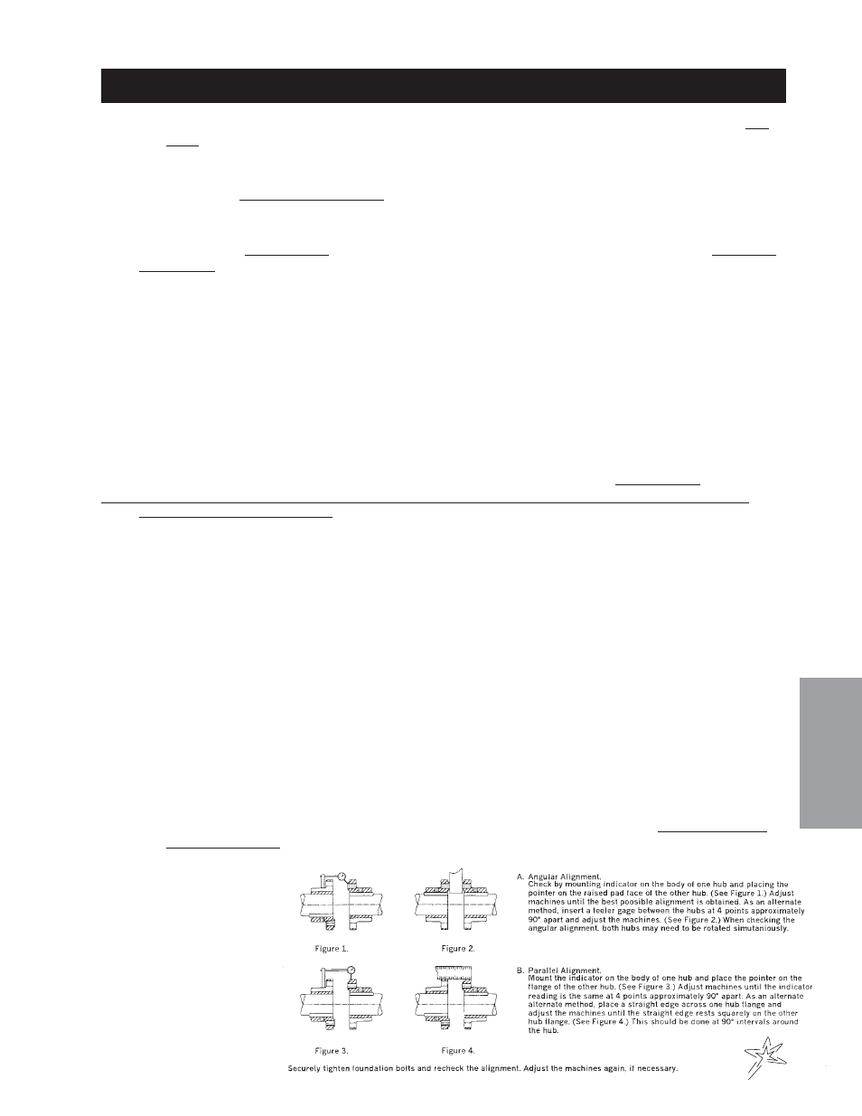
Check the Angular and Parallel Alignment (see Alignment Methods below). The Coupler alignment can be
adjusted by using the ½" Flat Washers (Ref # 50) to shim the Blower Mount Brackets and by adjusting
them vertically where they mount to the Mainframe. Secure set screws using Loctite® #262 and tighten.
Note: The maximum angular misalignment is 3° and the maximum parallel misalignment is .04". Exceeding these
measurements will void warranty.
6.
Bolt Blower Mount Brackets to the Mainframe using the ½ - 13 x 1½ Bolts and ½ - 13 Whiz Lock Nuts
from the Rake Lift.
7.
After Coupler (Ref # 19) alignment is completed mount the Cylinder Stop (Ref # 13) along side the Rake
Lift Hydraulic Cylinder and secure using the ½ x 3 Clevis Pin (Ref # 14) and one
1
/
8
" Bridge Pin (Ref # 15)
as illustrated. Secure the free end of the Hydraulic Cylinder and the Cylinder Stop to the Blower Mount
Bracket (Ref # 8) using the ¾ x 2
½
Clevis Pin (Ref # 11) and the other
1
/
8
" Bridge Pin.
8.
To install the Wire Harness start by drilling a ½" hole in the control panel area on the left hand side of the
machine. Position this hole between the 2WD/3WD switch hole and the "M
ADE
IN
THE
USA" logo. Con-
nect wires to toggle switch and mount in hole. Install Switch Boot over switch. Plug wire harness into
Electric Clutch (Ref # 43). Connect black wire (-) to engine block and red wire (+) to the switch. Connect
one end of the single red wire to the switch and connect the other end to the 30 Amp circuit breaker. See
wiring diagram for illustration.
9.
Install Muffler Extension (Ref # 9) onto the muffler pipe using the Muffler Clamp (Ref # 10).
10.
Install the Park Brake Bracket (Ref #29) by bolting onto the Blower Mount Bracket (Ref # 8) using the
3
/
8
-
16 x 1¼ Bolts (Ref # 2). Secure with
3
/
8
- 16 Whiz Lock Nuts. Slide Blower Stands (Ref #'s 7&16) up for
transport and secure in place. This must be done to prevent damage to the machine components.
11.
Check all fasteners for proper installation, tighten any loose connections. All guards must be in place
and properly fastened before operation. The Cylinder Stop (Ref # 13) must be installed.
12.
The engine must be
running at full throttle
to prevent stalling the
engine when engaging
the clutch.
13.
The Belt Tensioner
must be maintained at
the 25° mark for
optimum performance.
- Super Star 42-00x (sn 4765 – 4840/12663 – 12711) Parts & Service Manual Super Star 42-00x (sn 4661 – 4691/12628 – 12655) Parts & Service Manual Super Star 42-00x (sn 4692 – 4764/12656 – 12663) Parts & Service Manual Super Star 42-00x (sn 4985 – 5260/12800 – 12969) Parts & Service Manual Super Star 42-00x (sn 5261 – 5340/12970 – 13039) Parts & Service Manual