SONOSAX SX-VT Quick_Start User Manual
Page 9
SONOSAX SX-ST RECORDER
Quick Start Guide
Page 9 of 26
3.2 MAIN DISPLAYS
3.3 INPUT CHANNELS VS RECORDER TRACKS
When the booting procedure is completed, the main screen displays the modulometers of the inputs channels
as well as main information's related to the set up of the recorder.
The main screen displays either the modulometers of the audio channels at the inputs or the recorder (which
means the audio outputted by the A/D Converters) or the modulometers of the recorder's tracks (see
examples below). Touching the blue region at the bottom of the screen toggles the metering of the Inputs
channels or the metering of the recorder's Tracks.
For sake of clarity in reading this manual, please note that:
- Inputs or channels: always refer to a physical input or output of the analogue mixer or of the A/D Converter
- In the next chapters, the word "Input" always refers to the digital audio applied at the input of the recorder
- Tracks: always refer to a virtual track of the recorder
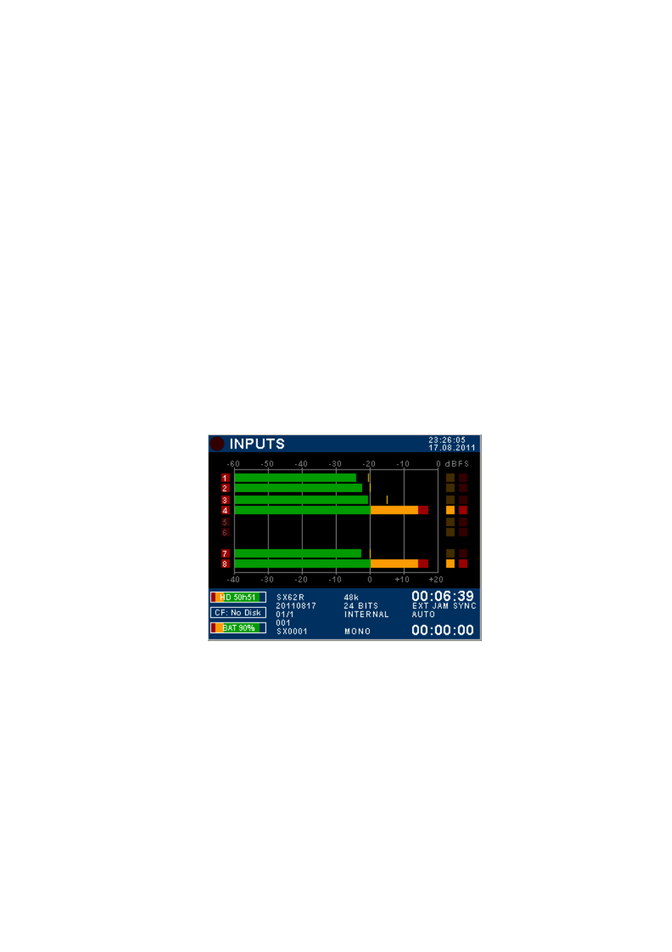
3.4 INPUTS MODULOMETERS
When the screen shows the INPUTS modulometers, numbers 1 to 8 represent the digital audio applied at the
input of the recorder; this means the audio channels fed from the output of the A/D Converter. Obviously the
audio depends on selected source the A/D Converter (either the direct out of the channels or main Mix buses)
- On the first column, the numbering from 1 to 8 represents the number of the input channels
- High-lighted Red square indicates that an input channel is assigned on an armed track, ready to record
- A dimmed Red square means that no input is assigned and/or the track is not armed.
Input channels modulometers
System Date & Time
Digital scale in dBFs
High lighted Red squares on
input channels 1 to 4 = the
inputs are routed on armed
tracks
5 & 6 are dimmed = input
channels are not routed or the
tracks are not armed
Red Dot = Overload
Inputs 7 & 8 are routed on
armed tracks
Digital scale below the
designed reference level
Remaining capacity on HD
Time Code value
Remaining capacity on CF
Time Code Synchronisation
Battery or external level indicator
(in volts)
Elapsed time
STREC =
20110817=
01/1 =
001 =
SX0001 =
Project name
Working Day
Scene name
Take number
Filetag
Sampling Frequency
Resolution (Bits per sample)
Audio Sync mode
Audio File format