Ac mains power – Studio Technologies 42A 2008 User Manual
Page 12
Issue 1, February 2008
Model 42A User Guide
Page 12
Studio Technologies, Inc.
The type of interconnecting cable used
between the Model 42A’s IFB circuits and
the user devices will vary by application.
In a fixed installation it would be typical
to use 22 AWG, shielded, stranded cable
in either a single- or 2-pair configuration.
With single-pair cable, pin 1 should be
connected to shield. Pins 2 and 3 would
connect to the cable pair.
If 2-pair cable is used, pin 1 should con-
nect to one side of each pair, with pin 2
going to one side of pair one and pin 3
going to one side of pair two. The shields
can either go only to the XLR connec-
tor shells, or to both the connector shells
and pin 1. Shielding unbalanced audio
signals can be a tricky proposition. It is
recommended that the focus be on using
excellent twisted-pair cable, rather than
worrying about whether or not it is shield-
ed. The typical foil shields used in much
of the contemporary audio cable generally
offers very limited effectiveness. The best
rule to follow is to try to minimize exposure
to large noise sources. (Okay, so that’s
hardly ever practical but at least it’s a nice
dream!)
In the event that very long cable runs are
required, the resistance of the cable can
impact the DC power supplied by the
Model 42A. There’s no way to get around
the fact that some DC voltage will be
dropped by the interconnecting cable. A
simple “ohms law” calculation will tell you
the impact a specific cable run will have.
You’ll need to know the current draw of the
connected device(s), the minimum volt-
age required by the connected device(s),
and the resistance of the cable’s conduc-
tors. This is generally stated as ohms per
1000 feet. Make sure that you account for
the resistance in both the pin 1 and pin 2
legs! In general, if there is the potential for
a cable-length problem, moving to a more
substantial cable gauge, such as 20, 18,
or 16 can be effective.
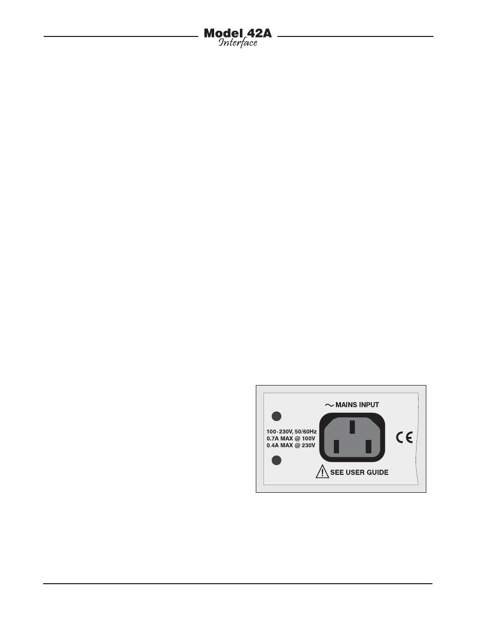
AC Mains Power
The Model 42A operates directly from AC
mains power of 100 to 230 V, 50/60 Hz.
Being a “universal input” device, there
are no switches to set or jumpers to in-
stall to match a location’s nominal mains
voltage. For locations that have a mains
power source of 240 volts, contact Studio
Technologies for confirmation that a direct
connection can be made.
The Model 42A uses a 3-pin IEC 320
C14-type inlet connector to mate with a
detachable mains cord. For units shipped
to North America and Japan a cord is
supplied that has a North-American
(NEMA 15L) standard plug on one end
and an IEC 320 C13-type connector on
the other. Units bound for other destina-
tions require that the appropriate cord be
obtained.
Figure 6. Detail of back panel showing AC
mains power connector