Technical notes, Software version number, Cable length – Studio Technologies 42A 2008 User Manual
Page 19
Model 42A User Guide
Issue 2, February 2008
Studio Technologies, Inc.
Page 19
3-pin XLR-type connector. Connect pin 1
on both connectors together. Connect pin
3 on both connectors together. Connect
separate wires to the pin 2 leads on both
connectors. Then connect the meter leads
to these two wires. The meter will indicate
the DC current being drawn while normal
operation of the connected device(s) takes
place. Be certain to connect the maximum
number of devices that might be powered
by the IFB circuit. That is, measure the
worst-case condition and ensure that the
load is within the rated 200 milliamperes
output. If possible, leaving a 10 or 20%
reserve margin is a good practice.
Technical Notes
Software Version Number
The Model 42A includes a special power-
up sequence allows the software version
number to be displayed. This is useful
when working with factory personnel on
applications support and troubleshooting
situations. The four IFB circuit status LEDs
are used to display the software version
number with a range of 1 through 4.
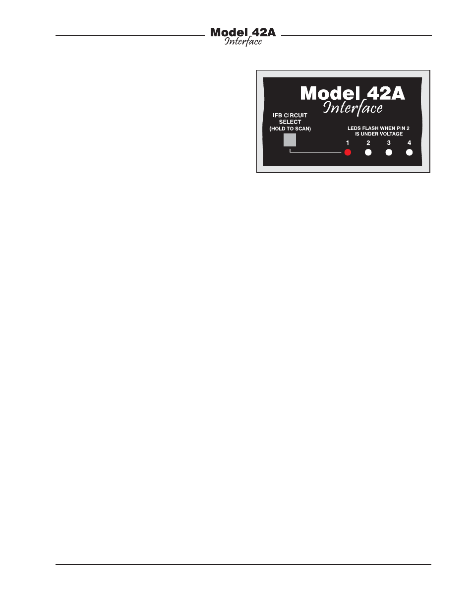
Refer to Figure 10 for a detailed view of
the LEDs and the corresponding software
version numbering scheme. The Model
42A’s initial software release is version 1.1.
This is represented by the LED on the far
left side being lit. Future software releases
will increment this number.
To display the Model 42A’s software ver-
sion is very simple. From the powered-
down state, press and hold the front-panel
pushbutton switch. Apply mains power
while continuing to press the button. The
normal power-up sequence will not oc-
cur but instead one of the status LEDs will
light. After the software version number
has been “read” the pushbutton can be
released. At this time the unit will begin
its normal power-up sequence.
Note that while it’s easy to determine
which software version is loaded into the
Model 42A a replacement microcontroller
integrated circuit is required to update it.
Contact the factory for details.
Cable Length
There are no hard and fast rules defining
the maximum cable length possible when
connecting user devices to Model 42A
IFB circuits. The maximum cable length is
directly related to the amount of resistance
in the connecting cable; the lower the
resistance per foot (or meter), the longer
the cable can be. (Although cable capaci-
tance affects high-frequency performance,
resistance is the limiting factor in this
case.) For example, a traditional 20 AWG
microphone-type cable is Belden 8412,
which has 10.9 ohms resistance per con-
ductor per 1000 feet. Since we’re using
two conductors to carry the signal (pins 1
and 2) you’d get 21.8 ohms per 1000 feet
of cable. By knowing the cable resistance
value, along with the minimum voltage
and maximum load current required by
Figure 10. Detail of front panel showing the
status LEDs that display software version. In
this example, the software version is 1.1.