5 step 2: wiring, 6 terminal layout series 3l indicators, Step 2: wiring – Super Systems 3L Series User Manual
Page 6: Terminal layout series 3l indicators, Series 3l
Advertising
Operations Manual
Series 3L
6
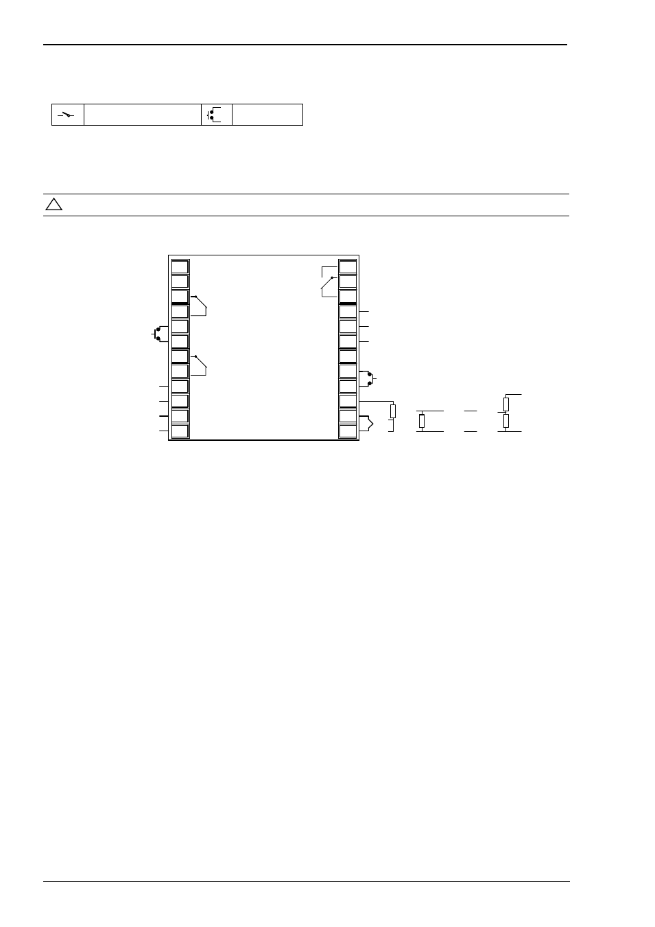
1.5 Step 2: Wiring
Key to Symbols used in the wiring diagrams
Relay Output
Contact Input
1.6 Terminal Layout Series 3L Indicators
!
Ensure that you have the correct supply for your indicator. Check order code of the indicator supplied
1A
1B
LB
LC
3A
3B
3C
3D
L
N
AA
AB
AC
HD
HE
HF
CT
C
LA
VI
V+
V-
Series 3L
+
24V
_
COM
A(+)
B(-)
Output 1 (OP1)
Digital Input B
Output 3 (OP3)
24V Transmitter Supply
Line Supply
100 to 230Vac ±15%
48 to 62 Hz
+
-
AA Relay (OP4)
FM RElay
Digital
Communications
EIA 485
Digital Input A
2.49
Ω
+
-
+
-
100K
Ω
806
Ω
+
-
10V Input
T/C Pt100 mA mV Vots
Sensor Input
Advertising