Appendix b multiple controller wiring diagram – TE Technology TC-24-25 User Manual
Page 17
17
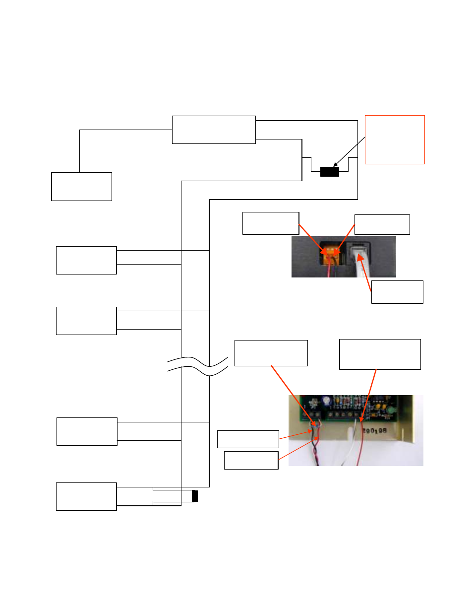
APPENDIX B Multiple Controller Wiring Diagram
COMP UTER
COMP UTER
RS-232 TO RS -485
CONVERTE R
RS-232 TO RS -485
CONVERTE R
TC-24-25
UNIT #1
TC-24-25
UNIT #1
TC-24-25
UNIT #2
TC-24-25
UNIT #2
TC-24-25
UNIT #30
TC-24-25
UNIT #30
TC-24-25
UNIT #31
TC-24-25
UNIT #31
120 OHMS
+ PIN 3
–
PIN 2
RS-485 PORT #1
(ORANGE WAGO CONNECTOR)
RS-232 (COMM PORT)
RS-232 PORT
(RJ11 CONNECTOR)
PIN 1 – CTS
PIN 2 – RTS
PIN 3 – COM
PIN 4 – TXD
PIN 5 – RXD
PIN 6 – DSR
PIN OUTS PROVIDED FOR
REFERENCE ONLY
RS-485 PORT #2
RS-485 PORT #3
RS-485 PORT #31
RS-485 PORT #32
+
–
+
–
+
–
+ (red wire)
–
(black wire)
If using the supplied
RS-232 to RS-485
converter, this 120
ohm resistor is already
installed within the
converter itself.
120 OHMS
Picture of Converter
PIN 3 RS -485
(RE D WIRE )
PIN 2 RS -485
(BLACK WIRE)
RJ11
RS-232 PORT
Picture of TC-24-25
Thermistor wires to
JP1-5 and JP1-6
(Polarity not important)
Terminating Resistor
from JP3-3 to JP3-2
BLACK WIRE FROM
RS-485 TO JP3-2
RED WIRE FROM
RS-485 TO JP3-3