Lcf/pfl switch, Side view, Front view – Teac KS-6001 User Manual
Page 8: Ks-6001, Indicator input selector (x 4)
8
KS-6001
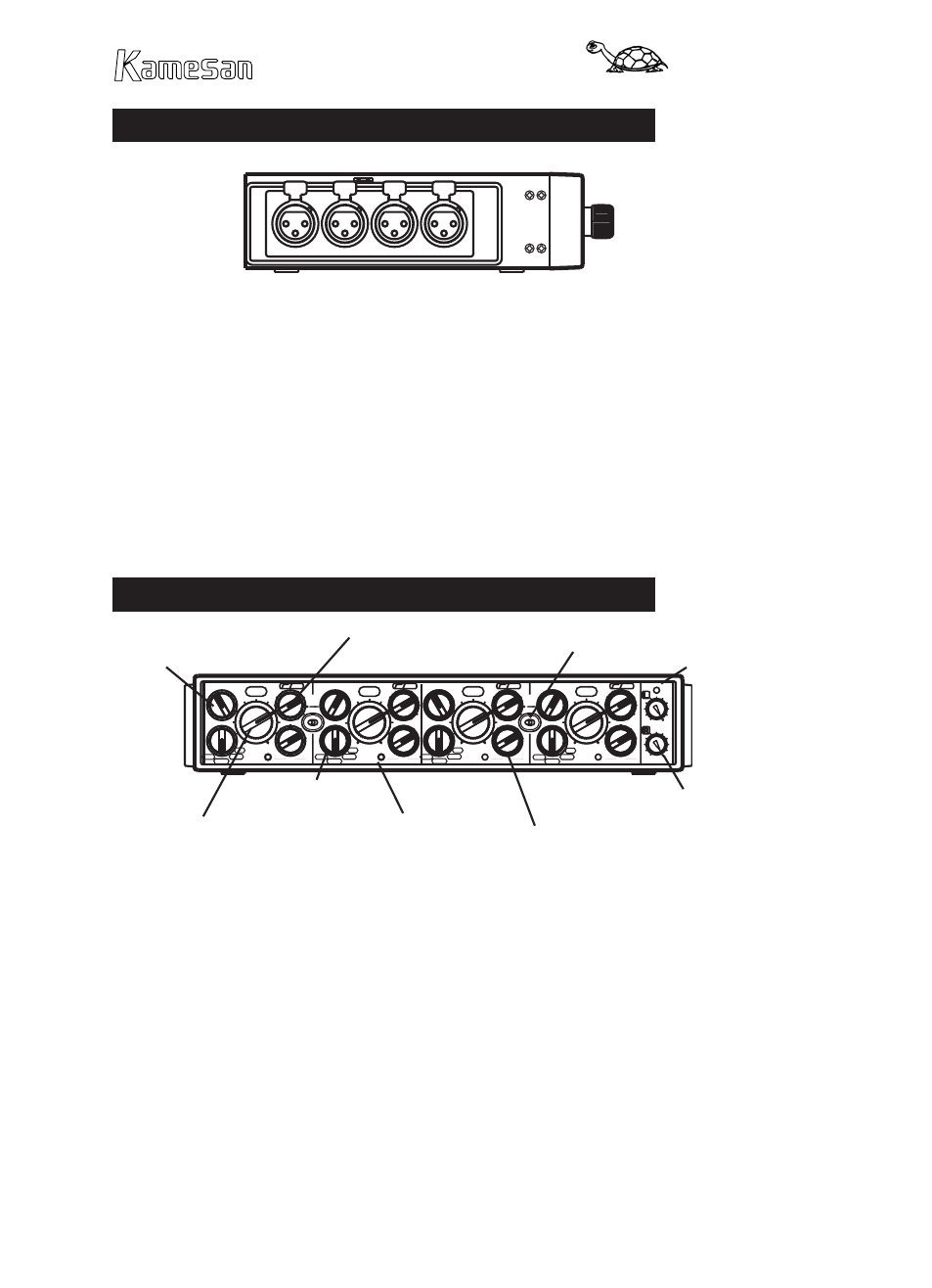
Side view
The four XLR male connectors are used to connect appropriate
microphones (or line-level sources) to the unit. Always ensure
that microphones or line sources are correctly selected using
the front panel selection switch, in order to avoid possible dam-
age to the sources or to the KS-6001.
The XLR connectors are wired in the standard 1=ground, 2=hot,
3=cold configuration.
There is also a locking lever visible on this side which should
be used together with its counterpart on the other side when at-
taching or detaching the KS-6001 to or from another unit.
Front view
POWER
PEAK
PEAK
PEAK
PEAK
FD
LINK
FD
LINK
0
0
2
L
F
P
R
L C
0
0
2
-70
-30
-20
+4
L
F
P
R
L C
0
0
2
L
F
P
R
L C
0
0
2
L
F
P
R
L C
LINE
Dy-M
P-48
A-B
-70
-30
-20
+4
-70
-30
-20
+4
-70
-30
-20
+4
LINE
Dy-M
P-48
A-B
LINE
Dy-M
P-48
A-B
LINE
Dy-M
P-48
A-B
LCF/PFL switch
Use this control to sweep the low-cut filter fre-
quency (–12dB/octave) between 20Hz and 200Hz.
Though there is no way to turn this filter off, in practice, setting
the cutoff frequency to 20 Hz has the same effect as turning it
off, as most microphone systems are not sensitive to sounds in
that frequency range.
Press this control (it is non-latching) to perform a pre-fade lis-
ten (PFL) on the channel (only when connected to the KS-342,
through the KS-342’s headphone monitoring system). More
than one of these PFL controls can be pressed at the same time,
LCF/PFL switch (x 4)
Channel fader (x 4)
Output bus
assignment (x4)
Peak indicator (x 4)
Input trim control (x 4)
Master faders
Fader link (x 2)
Power
indicator
Input selector (x 4)