Tecfluid LC Series User Manual
Page 3
3
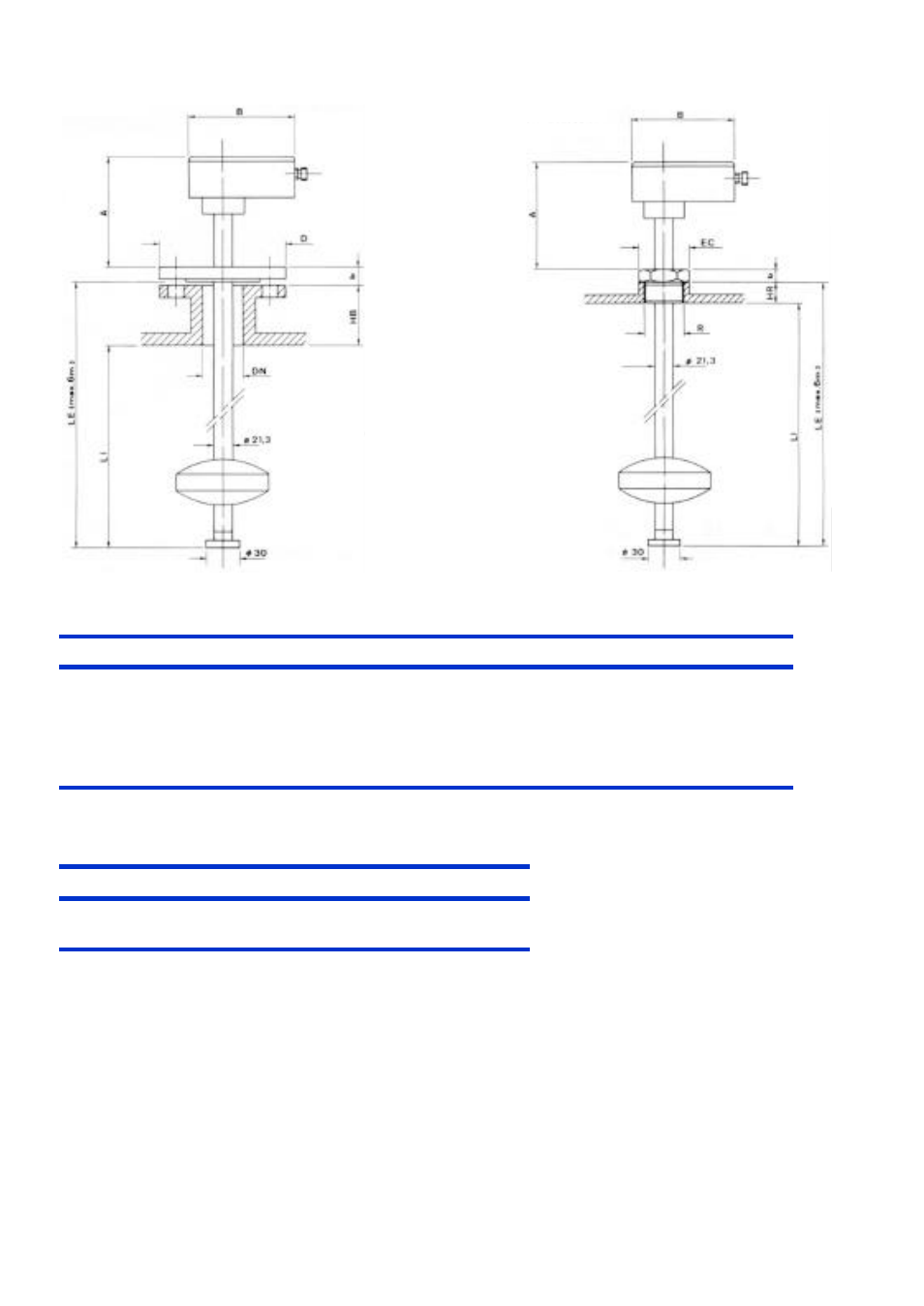
DIMENSIONS
LC-30
LC-31
LC-30
DN
PN
D
k
g
Lxno.
b
A
B
HB
LE
LI
25*
40
115
85
68
14x4
18
160
125
40
16
150
110
88
18x4
18
160
125
100*
16
220
180
158
18x8
20
160
125
150*
16
285
240
212
23x8
22
160
125
Related to the
individual measuring
range.
LC-31
R
EC
b
A
B
HR
LE
LI
1 ½”
60
22
160
125
30
Related to
range
( * on request )
The wiring should be made according to the attached diagram.
When using inductive loads, such as relays or electro-valve coils, surge arresters should be
installed to protect the reed contacts.
With a dc supply, a diode should be used.
For an ac supply, an RC circuit can be used as shown, although a varistor (VDR) is better and is
easier to select the right value.
The VDR should have a breakdown voltage greater than 1.5 times the rms voltage.
The standard varistor ratings specify the rms working voltage for the varistor, for example a
S05K25 varistor will be for 25 V
rms
working and will have a breakdown voltage of 39 V at 1 mA.
WIRING