Velocity kvm-35, Quick start guide, Multi-mode fiber extension – three dvi displays – Thinklogical Velocitykvm-5 Quick Start Guide User Manual
Page 2: Velocitykvm-35 transmitter velocitykvm-35 receiver, Multi-mode fiber-optic cable guide, Dvi display 1 2 3
1 0 0 - 2 4 0 V - , 0 . 5 A , 5 0 / 6 0 H z
T 2 A , 2 5 0 V A C
C A U T I O N ! R e p l a c e w i t h s a m e t y p e a n d r a t i n g f u s e .
C N T R L
L I N E O U T
H O S T
U S B H I D
U
P
D
A
T
E
S
P W R
F O L
U S B 2 . 0
S E R I A L P O R T
D V I O U T 1
D V I O U T 2
D V I O U T 3
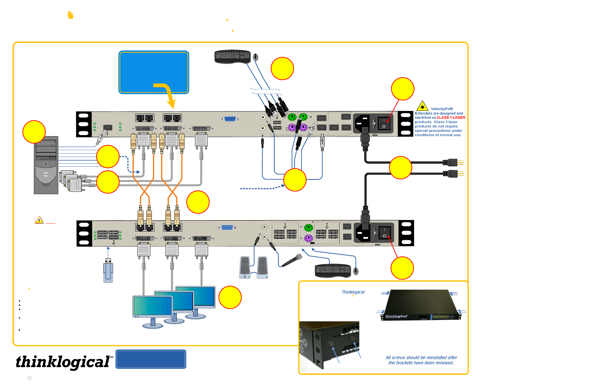
STEP 6: Three DVI-D cables (CBL-000009-002MR) are
included. Connect one each to the CPU’s DVI 1, 2 and 3
Video Cards and the other ends to the VelocityKVM
Transmitter’s DVI IN 1, 2 and 3 ports.
U P D A T E S
D E V
D V I I N 2
D V I I N 3
D V I I N 1
S E R I A L P O R T
L 2 L 3
L I N E I N
M I C O U T
H I D
P
S
2
P
S
2
L O C A L
F R O M C P U
U S B 1 . 1
U S B 1 . 1
U S B H I D
H O S T
C N T R L
C A U T I O N ! R e p l a c e w i t h s a m e t y p e a n d r a t i n g f u s e .
1 0 0 - 2 4 0 V - , 0 . 5 A , 5 0 / 6 0 H z
T 2 A , 2 5 0 V A C
C L I N K
P W R
C P
F O L
6
4
3
U S B 2 . 0
A u d i o O U T ►
A u d i o I N ◄
P S / 2 K e y b o a r d
P S / 2 M o u s e
U S B H I D ( K y b d / M o u s e )
U S B 1 . 1 ( K y b d / M o u s e )
PS/2
Kybd/
Mouse
USB
HID
USB 1.1
8
▲
Audio
OUT
5
2
3
VelocityKVM-35 Transmitter
VelocityKVM-35 Receiver
STEP 7: If desired, connect your local
keyboard and mouse by inserting the PS/2 or
USB HID connectors into the VelocityKVM
Transmitter’s local devices receptacles.
STEP 4: Connect your Multi-Mode Fiber
Optic cables between the Transmitter
and Receiver units.
STEP 5: Connect
your KVM devices
to the CPU using
the cables supplied
in KIT-000005-R.
STEP 3: Turn the
Receiver unit ON (1).
STEP 2: Connect your desktop
devices (monitors, keyboard,
mouse, etc.) to the Receiver
using standard cables.
Each Thinklogical™ Velocity
kvm-35
Multi-Mode Fiber Optic System consists of a transmitter unit and a receiver unit connected by four multi-
mode fiber optic cables. The transmitter unit connects to the computer with standard cables and the receiver unit provides connections to the user
interface devices. The Velocity
kvm-35
supports PS/2, full duplex stereo audio, serial (RS-232), USB 1.0 (HID) device ports and USB 1.1. USB
2.0 (high speed up to 480Mbps) is optional.
Note: Be sure to
leave adequate ventilation
space on both sides of the
units (2” minimum),
especially if the units are
being stacked
CONTENTS
Upon receiving your Thinklogical
Velocity
kvm-35
Extender, you
should find the following items:
7
Local PS/2
Connectors
Local USB HID
Connectors
9
STEP 9: Turn on the Source
(CPU) last. Verify that all
system features are
functioning properly.
Visit us online at
www.thinklogical.com
for more
product information, current updates and the
complete line of Thinklogical™ products.
T M
M I C I N
Copyright c 2009. All rights reserved. Printed in the U.S.A. All trademarks and service marks are the property of their respective owners.
8 Mounting bracket
screws
Th ree Head Sing le Link
Velocity
kvm-35
Fiber Op tic Tran smitt er
2 Mounting bracket screws
in four places.
RACK-MOUNT OR DESK-TOP
OPTIONS: Like all
™
KVM extenders, the
Velocity
KVM-35
can be mounted in a standard EIA 19"
rack or on a shelf or desk-top.
Each mounting bracket is secured
by four screws and can be safely
removed from the transmitter or
receiver unit for desk-top mounting
after power has been removed from
the unit.
Velocity
kvm-35
L 1
L 4
VelocityKVM Extender Transmitter
VelocityKVM Extender Receiver
2 AC power cords, PWR-000006-R
(International connections may differ.)
VelocityKVM Extender Cables:
3 DVI-D Male Cables, 2 meters, CBL-000009-002MR
1 Cable Kit (8 six ft. peripheral cables.) KIT-000005-R
VelocityKVM Extender Product Manual
All physical connections to the product use industry-standard connectors.
STEP 8: Turn the
Transmitter unit ON (1).
Multi-Mode Fiber-Optic
Cable Guide:
L1: Data Tx to Rx and Video 1
L2: Data Rx to Tx
L3: Video 2
L4: Video 3
QUICK START
GUIDE
Multi-Mode Fiber Extension – Three DVI Displays
PS/2 or USB
connectors
L 2
L 3
L 1 L 4
Audio IN►
5
DVI
Display 1
2
3
PHONE:
(800) 291-3211
WEBSITE: www.thinklogical.com
EMAIL:
L 2
L 1
L 2
L 1
L 4
L 4
VELOCITY-35_Quick_Start_Rev_B
L 3
L 3
STEP 1: Ensure that the POWER ON/OFF switch is
in the OFF position (0) on both the Tx and Rx units.
Connect the supplied AC Power Cords to both units
and plug them into a standard AC supply. LEAVE
BOTH SWITCHES IN THE OFF POSITION.
1