Tri Tool 206B Miter Mandrel User Manual
Page 11
11
Model 206B-MM, Miter Mandrel
92-0448 : Orig. 930630
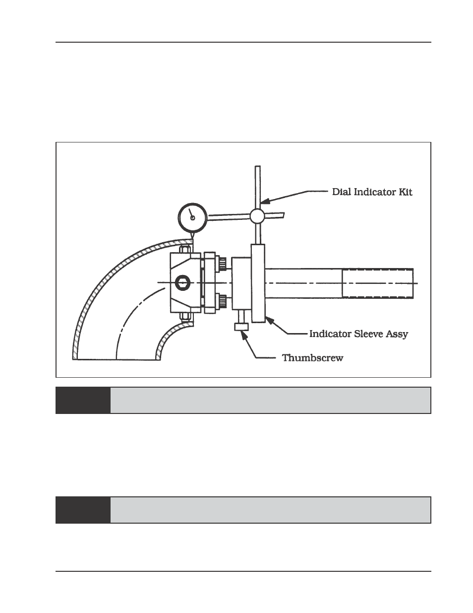
NOTE:
NOTE:
If the existing surface of the workpiece is to be used for alignment and centering
references, use the Dial Indicator and hardware provided.
If punch marks, scribe lines, or other references are to be used, simply select the
required hardware from the Indicator Kit to be used as a pointer.
The first adjustment to be made after mounting is always the angular off-set.
Mounting the Indicator Kit on the Mandrel
Changing the angular offset will always change the parallel offset, but
changing the parallel offset will not change the angular offset.
To move the Mandrel Shaft in a given direction, one or two Angular Offset
Adjustment Screws in the opposite direction of movement must be loosened enough
to allow the amount of movement anticipated.
Then the Angular Offset Adjustment Screws directly across must be retightened to
draw the Mandrel Shaft in the desired direction.
Never exceed 40 ft-lbs. (54 N-m) of torque on the angular offset Adjustment
Screws.
Repeat the indicating procedure and the angular offset procedure as many times as
necessary to achieve the accuracy desired.