Tri Tool 206B Miter Mandrel User Manual
Page 12
12
TRI TOOL INC.
92-0448 : Orig. 930630
WARNING:
NOTE:
Evenly torque all (4) four Angular Offset Adjustment Screws.
Now the parallel offset adjustment may be made.
As before, use the Indicator Kit to determine how much the Mandrel Shaft must
move, and in what direction.
To move the Mandrel Shaft in a given direction, first loosen the Jackscrew on the
side you wish to move toward.
Now tighten the Jackscrew on the opposite side of the Head Assy., which you wish
to move away from in order to push the Mandrel Shaft in a given direction.
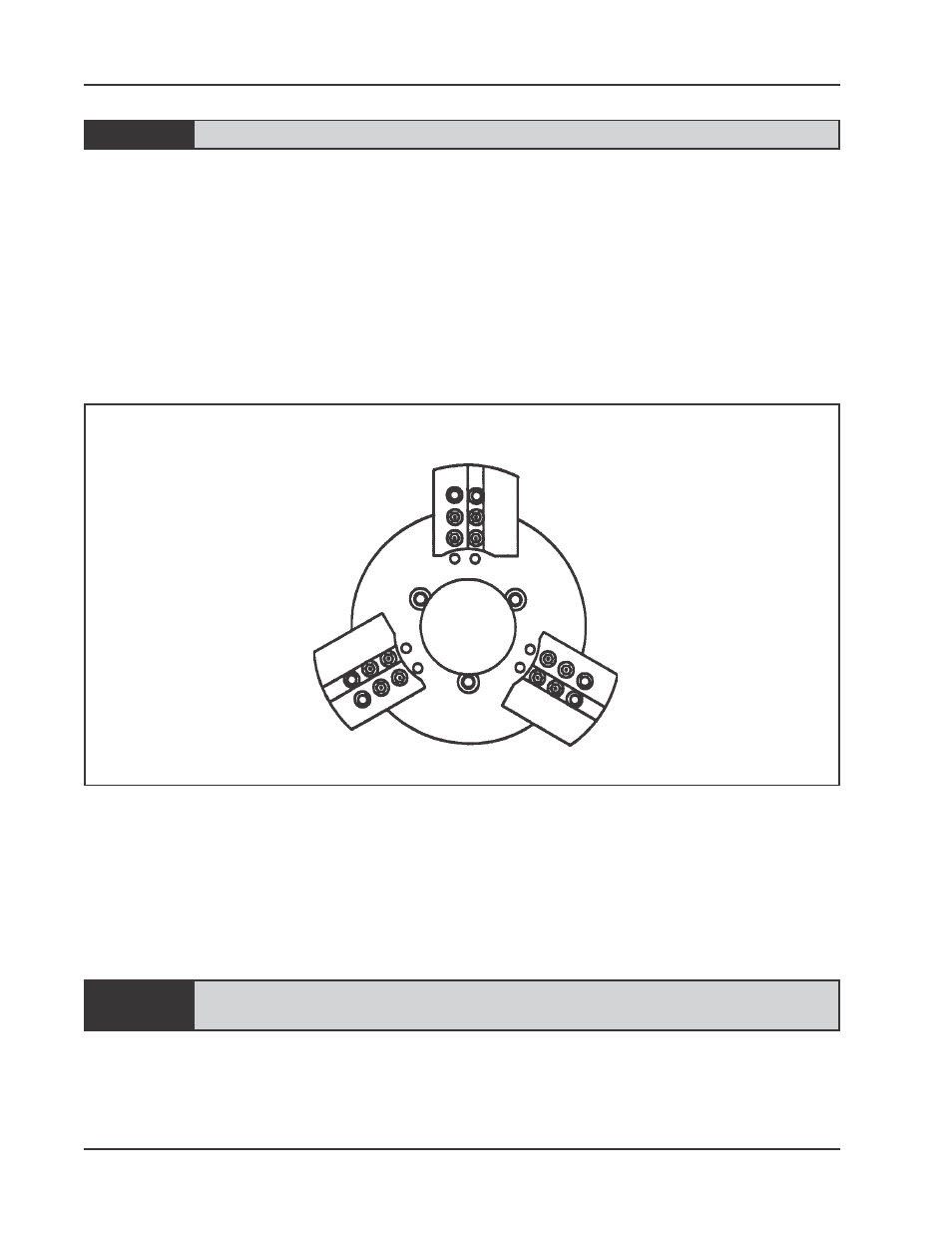
Tool Block Position when using the Miter Mandrel
Repeat the indicating procedure and the parallel offset adjustment procedure as
many times as necessary to achieve the accuracy desired.
Remove the Indicator Kit from the Mandrel Shaft.
Before installing the Model 206B, be sure to read the Operator’s Manual for that
machine carefully, giving special attention to all safety cautions and warnings.
The Tool Block on the Model 206B must be mounted using the four outer
most bolt holes so that they will clear the Miter Head.