Verilink 1041 (CG) Configuration/Installation Guide User Manual
1041 redundant power shelf, Configuration guide, Installation
Installation
The TxPORT 1041 Redundant Power Supply
Shelf is designed to hold either one or two
power supplies conforming to industry standard
Type 400 mechanics (such as TxPORT’s model
number 9-1000-48V-2). The shelf provides
wiring from the power supply connectors to an
AC power input. Fused DC output terminals are
located on the rear of the shelf.
Rack mounting ears are available for installation
into standard 19" or 23" racks. To install the ears
onto the 1041, use the 2 tapped screw holes on
each side of the 1041. To install the 1041 into a
rack, insert two screws through both the left and
right mounting brackets.
The 1041 shelf has two slots accessible from the
front in which the power supplies are inserted. To
install the power supplies, first remove the front
panel by removing the two screws. Then insert
each supply through one of the two slots until the
card is firmly seated to the rear connector.
AC power is applied to the unit by inserting the
power cord into a 110 V outlet. DC power is then
derived from the unit by connection to the rear
panel terminal strips.
1041 POWER SUPPLY
Specifications
Input Voltage:
115 VAC (± 20 V)
Output Voltage:
48 VDC (± 2 V)
Output Current:
2 A maximum, 50 mA minimum
Power Input:
113 W maximum
Heat Generation:
390 BTU
Efficiency:
80%
Alarm Contact
1.0 A @ 220 VDC
Ratings:
1.0 A @ 250 VAC
Mechanical:
16.5" W, 1.625" H, 6" D
4.5 pounds with no power supplies
7 pounds with two power supplies
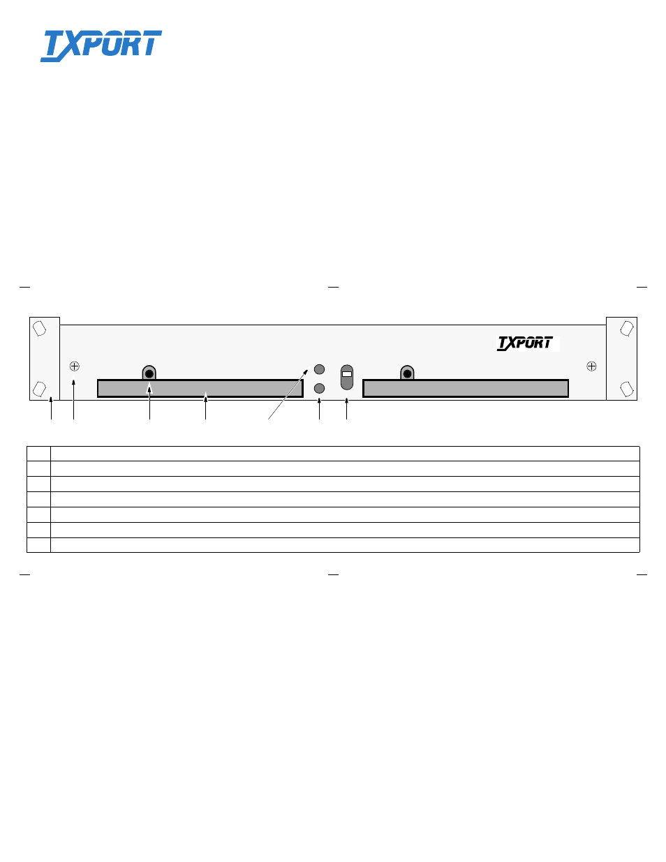
Front View
ALARM
CUTOFF
ACO
ALARM
P/S A
P/S B
WARNING: Use caution when installing or
removing the power supplies. 110 volts AC is
present on the inside rear circuitry.
When installing a power supply with AC power
connected, the ‘Alarm’ LED will light for about
10 seconds while the unit stabilizes (undergoes a
soft start). The green power indicator then lights
if the unit is operating normally.
WARNING: When replacing one of the power
supplies while in service, wait at least 10 min-
utes after removing the supply before replacing
the new one. This prevents contact arcing of the
edge connector.
1
Mounting Bracket: Rack mounting ears are available for installation into standard 19" or 23" racks.
2
Panel Screw: These two screws are used to mount the front panel to the 1041 housing.
3
Power Indicator: This green indicator lights when the 1041 power shelf has 110 VAC applied to it and operation is normal.
4
Power Supply: Power supplies ‘P/S A’ and ‘P/S B’ are inserted into these 2 openings.
5
ACO: This yellow LED lights if the Alarm Cut Off switch is placed in the upper ‘ON’ position, indicating that the alarm relay contacts are disabled.
6
Alarm: This red LED lights if any fuse opens or if one of the redundant power supplies fails (this can be cleared by removing the supply).
7
Alarm Cutoff: This switch controls the alarm relay contacts. If it is placed in the upper ‘ON’ position, the alarm relay circuitry is deactivated.
2
4
3
6
7
Ordering Numbers
The part number for the 1041 Shelf
(dual 400 plug-in shelf) without any
power supplies is:
F -1041-000--110
The part number for the 48 VDC
power supply is:
9-1000-48V-2
T
R
A
N
S
P
O
R
T
®
1041 Redundant Power Shelf
Configuration Guide
Part Number 45- 00070
Rev 1.00
5
1
T
R
A
N
S
P
O
R
T
®