1042 power shelf rear panel rear panel description, Simplified schematic – Verilink 1042 (CG) Configuration/Installation Guide User Manual
Page 2
115 VAC
2.0A
60Hz
FUSE RATING
3.0A 125V
FUSE RATING
3.0A 125V
B
F1
A
F2
ELECTRIC SHOCK AND ENERGY HAZARDS, TO
COMPLETELY DEENERGIZE REQUIRES THE
DISCONNECTION OF THE AC AND DC SOURCE
REPLACE WITH SAME TYPE/RATING FUSE
+
PSA
48VDC
2A
ALARM
CONTACTS
NO
C
NC
+
PSB
48VDC
2A
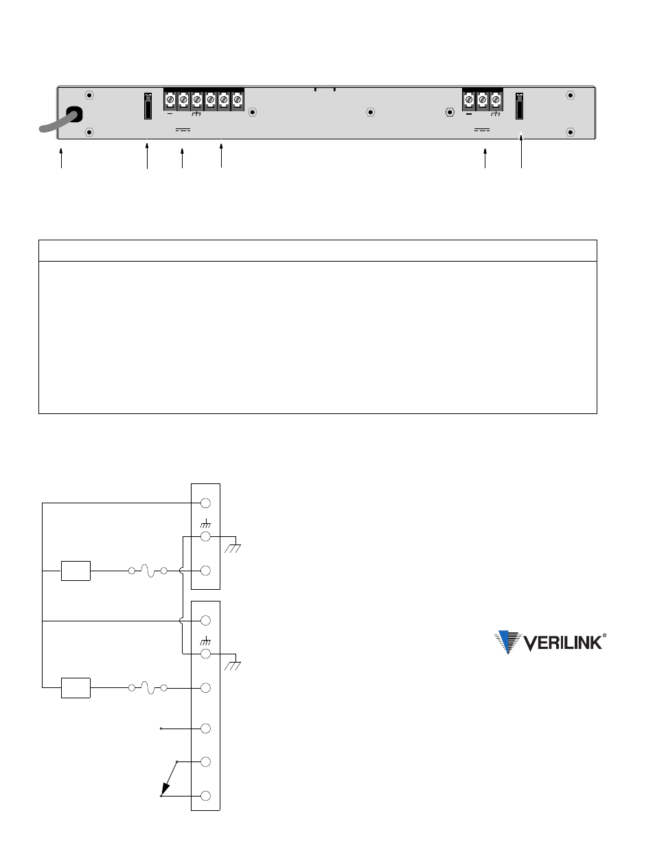
1042 Power Shelf Rear Panel
Rear Panel Description
2
3
1
4
5
Index
Function
1
AC Power Cord: This cord can be connected to any available 110-V outlet.
2
Fuse F1: This fuse protects power supply B (PS B) with a rating of 3 amperes.
3
PS B: The three screw terminals on the left are used to connect a
−
48-VDC load to the main feeds.
4
Alarm Contacts: The three isolated contacts on the right permit connection to a remote indicating device. The contacts may be
configured as normally closed (NC) or normally open (NO). NO and NC refer to the contact’s relationship to the common (C) contact
under a no alarms condition.
5
Fuse F2: This fuse protects power supply A (PS A) with a rating of 3 amperes.
6
PS A: These three screw terminals are used to connect a
−
48-VDC load to the main feeds.
PS A
PS B
-48 V
-48 V
F2
3 A
F1
3 A
+
–
•
•
Simplified Schematic
–
+
6
NO
C
NC
ALARM CONTACTS
TERMINAL STRIP A
TERMINAL STRIP B
145 Baytech Drive
San Jose, California 95134
127 Jetplex Circle
Madison, Alabama 35758
(800) 837-4546
www.verilink.com
FAX-On-Demand
(800) 957-5465
Technical Assistance Center
(800) 285-2755