Verilink 1050 (CG) Configuration/Installation Guide User Manual
1050 aps chassis, Configuration guide, 1050 chassis front view connections
T
R
A
N
S
P
O
R
T
®
1050 APS Chassis
Configuration Guide
Part Number 45- 00006
Rev 2.00
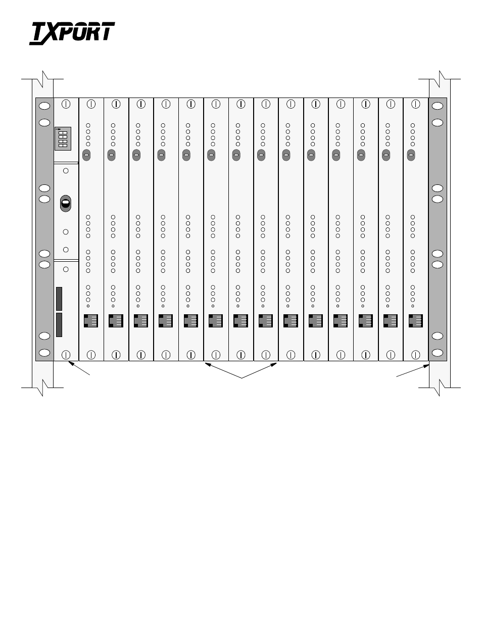
1557 APS Cards or 1554
Alarm and
0
1
2
3
4
5
6
7
8
9
10
11
12
13
14
Power Card
(Slot 0)
STATUS
PATH A
PATH B
LOS
TxPORT
1557
STATUS
PATH A
PATH B
LOS
TxPORT
1557
STATUS
PATH A
PATH B
LOS
TxPORT
1557
STATUS
PATH A
PATH B
LOS
TxPORT
1557
STATUS
PATH A
PATH B
LOS
TxPORT
1557
STATUS
PATH A
PATH B
LOS
TxPORT
1557
STATUS
PATH A
PATH B
LOS
TxPORT
1557
STATUS
PATH A
PATH B
LOS
TxPORT
1557
STATUS
PATH A
PATH B
LOS
TxPORT
1557
STATUS
PATH A
PATH B
LOS
TxPORT
1557
STATUS
PATH A
PATH B
LOS
TxPORT
1557
STATUS
PATH A
PATH B
LOS
TxPORT
1557
STATUS
PATH A
PATH B
LOS
TxPORT
1557
STATUS
PATH A
PATH B
LOS
TxPORT
1557
3 AMP
1
234
O
1
2
3
–
POWER
SILENT
TxPORT
1250
NORMAL
ALARM &
CHASSIS
ADDRESS
POWER
ACO
ALARM
FUSE
ALARM
A
B
GMT
DLIU Cards (Slots 1 - 14)
Refer to the diagram on the reverse side for the locations of the following
connectors.
Equipment: Primary (Path A) and Secondary (Path B) equipment con-
nection to the APS system may be made through standard 0.045 gauge
wire wrap pins or through 50-pin female miniature ribbon type connec-
tors. Equipment side signals for all 14 APS cards are gathered on a single
50-pin female miniature ribbon type connector for each path. Input con-
nectors are labeled J6 and J9. Output connectors are labeled J7 and J8.
Network: Primary (Path A) and Secondary (Path B) network connection
to the APS system may be made through standard 0.045 gauge wire wrap
pins or through 50- pin female miniature ribbon type connectors. Network
side signals for all 14 APS cards are gathered on a single 50-pin female
miniature ribbon type connector for each path. Input connectors are
labeled J1 and J4. Output connectors are labeled J2 and J3.
NMS Bus: The TxPORT 1559 APS Manager (APSM) is used to remotely
configure, control, and monitor the 1557 cards mounted in the APS chassis
as well as 1558 APS CPE installations. The manager communicates to the
1557 cards through a bus interface (P1 Bus In and P2 Bus Out). The 1559
APSM can communicate with up to 8 chassis (or up to 112 APS cards).
The OUT port (P2) is used only to connect one chassis to the next in a
‘daisy-chain’ fashion. It is an output only port.
Alarm: Connector J5 provides relay contacts for connection to a remote
indicating device. The alarm output of the Alarm and Power Card is also
available on terminal block TB1 and on the wire wrap connectors of the
Alarm and Power Card.
Power: The APS Chassis must be powered by an external -48 VDC
source capable of delivering 2-ampere maximum current. The chassis can
accommodate two - 48 VDC power sources if redundancy is desired. Con-
nect a ground lead to TB1-10 (Chassis Ground). Connect the other end of
the ground lead to a solid chassis ground. Connect the primary power sup-
ply return lead to TB1-2. If a secondary power supply is used, connect its
return lead to TB1-1. Connect the primary power supply 48 VDC lead to
TB1-4. If a secondary power supply is used, connect its 48 VDC lead to
TB1-3. 18- or 20 -gauge wire is recommended for power connections.
N
Rack and
Mounting
Hardware
1050 Chassis Front View
Connections