Verilink 1051-1 Chassis (CG) Configuration/Installation Guide User Manual
Specifications, Ordering numbers, Installation
T
R
A
N
S
P
O
R
T
®
1051-1 Chassis Configuration Guide
Part Number 45-00049
Rev 1.00
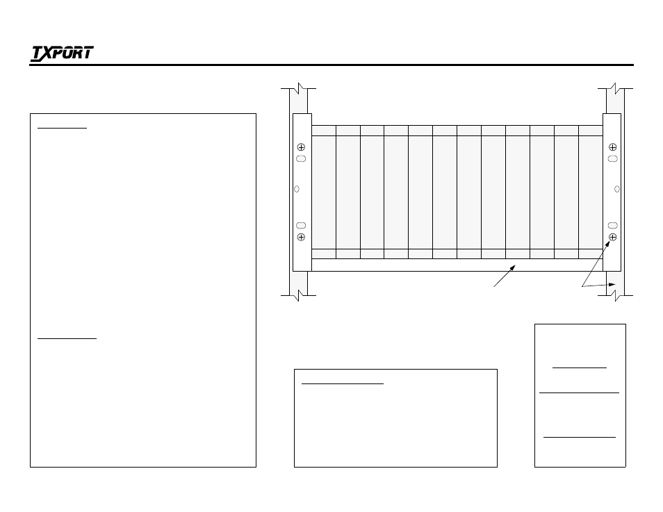
Rack and
19" or 23" Multiple
Line Chassis
Mounting Hardware
Model 1051 -1 Chassis, Front View
Unit
1
Unit
2
Unit
3
Unit
4
Unit
5
Unit
6
Unit
7
Unit
8
Unit
9
Unit
10
Unit
1
1
Unit
12
Specifications
Input Voltage:
115 VAC (± 20 V)
Output Voltage:
48 VDC (± 2 V)
Output Current:
2 A maximum, 50 mA minimum
Power Input:
113 W maximum
Heat Generation:
390 BTU
Efficiency:
80%
Mechanical:
17.2" W, 7" H, 10.5" D, 9.5 pounds
Ordering Numbers
Shelf without power supply:
9-1040-000--110
Shelf with one power supply:
9-1040-000--111
Shelf with two power supplies:
9-1040-000--112
Spare 48 V power supply:
9-1000-48V--1
Installation
The TxPORT 1051-1 chassis is designed to hold from one to
twelve TxPORT Model 2000, 2048, and/or 2100 CSU mod-
ules. The 1051-1 accommodates these modules with twelve
card slots open to the front of the chassis. Each module card
set interfaces a backplane board on the chassis rear through
two connectors. Through these card connectors, each module
receives a -48 VDC power source and exchanges control and
T1 input/output signals with the rear panel chassis connectors.
The chassis contains no active components.
Rack mounting ears are reversible for standard 19" or 23"
racks. To install, simply insert two screws through both the left
and the right mounting brackets.
The rear panel chassis connections are described on the
reverse side of this sheet.
TxPORT
127 Jetplex Circle
Madison, Alabama 35758
Customer Service
800-926- 0085, ext. 227
Product Technical Support
8 a.m. to 5 p.m. Central
205-772- 3770, ext. 256
800-285- 2755, ext. 256
Emergency After Hours
205-603-2193
Manager: 205-603-2194