1060 broadcast card rear panel, Rear panel description, Alarm / power pinout – Verilink 1060 Broadcast Card (CG) Configuration/Installation Guide User Manual
Page 2: Expand / t1 in pinout, T1 broadcast port pinout
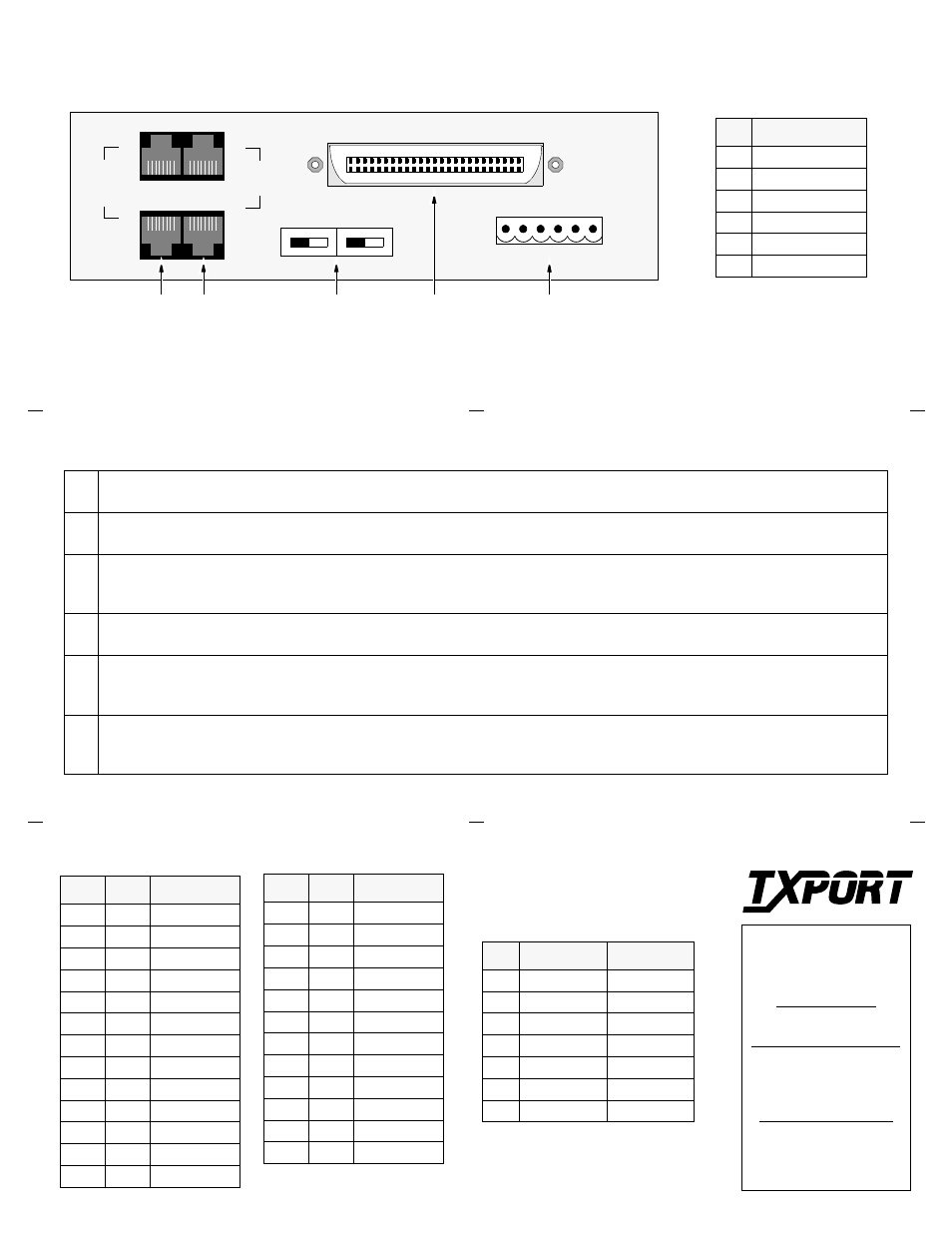
1060 Broadcast Card Rear Panel
8
1
Alarm / Power
8
1
6
1
1
8
1
8
TE
RM
UNTE
R
M
T1
IN
AB
4
8
VDC
18
0
M
A
EXP
AND
AB
Rear Panel Description
1
Expand: These two 8-pin modular jacks are used for jumping the ‘
A
’ or ‘
B
’ inputs together to provide additional inputs.
2
T1 IN: These two 8-pin modular jacks are used for the T1 input signal as well as the output of each input. These 2 connectors output
AIS with no input.
3
Terminate/Unterminate: These two slide switches are used for setting the ‘
A
’ or ‘
B
’ input. They are recessed and can be moved with a
screwdriver. ‘Terminate’ is used when the expansion connector is not used.
‘Unterminate’ is used when the expansion connector is daisy chained.
4
T1 Broadcast Port: This 50-pin female connector is used for the expanded outputs of either the ‘
A
’ or ‘
B
’ inputs. Refer to the pinout
table below.
5
Alarm: This 6-pin connector is used as follows for the alarm connection. The alarm connection is made on pins 2 and 5 to operate in a
normally closed mode (NC - opens on alarm) or on pins 2 and 6 to operate in a normally open mode (NO - closes on alarm). The contacts
are rated at 1.0 Amp AC or 1.0 Amp DC. 18 to 20 gauge wire is recommended.
5
Power: This 6-pin connector is used as follows for the power connection. The unit requires a -48 VDC power source that is capable of
supplying 50 mA current. Connect a chassis ground lead to pin 4. Connect the -48 VDC lead to pin 3. Connect the return lead to pin 1.
18 to 20 gauge wire is recommended.
1
2
3
4
5
A
B
Tip
Ring
Function
1
26
Output # 1
2
27
Output # 2
3
28
Output # 3
4
29
Output # 4
5
30
Output # 5
6
31
Output # 6
7
32
Output # 7
8
33
Output # 8
9
34
Output # 9
10
35
Output # 10
11
36
Output # 11
12
37
Output # 12
13
38
Output # 13
26
50
25
1
Alarm / Power Pinout
Pin
Function
1
48 VDC Return
2
Alarm Common
3
-48 VDC
4
Frame Ground
5
Normally Closed
6
Normally Open
Expand / T1 In Pinout
Pin
EXPAND
T1 IN
1
Data Out
Data In
2
Data Out
Data In
3
Not Used
Not Used
4
Not Used
Data Out
5
Not Used
Data Out
6
Not Used
Not Used
7, 8
Chassis Gnd
Chassis Gnd
14
39
Output # 14
15
40
Not Used
16
41
Not Used
17
42
Not Used
18
43
Not Used
19
44
Not Used
20
45
Not Used
21
46
Not Used
22
47
Not Used
23
48
Not Used
24
49
Not Used
25
50
Frame Gnd
Tip
Ring
Function
T1 Broadcast Port Pinout
TxPORT
127 Jetplex Circle
Madison, Alabama 35758
Customer Service
800-926-0085, ext. 227
Product Technical Support
(8 a.m. to 5 p.m. Central)
205-772-3770, ext. 255
800-285-2755, ext. 255
Emergency After Hours
205-603-2193
205-656-8318
Manager: 205-603-2194
T
R
A
N
S
P
O
R
T
®