Verilink 1060A Broadcast Card (CG) Configuration/Installation Guide User Manual
1060a broadcast card, Configuration guide, General
T
R
A
N
S
P
O
R
T
®
General
The TxPORT 1060A Broadcast card (part number F-
1060-100A-111) is used to expand a single T1 input to
14 T1 inputs where bridging may not be possible or
practical.
The inputs are redundant, switching from the Port A
to Port B or Port B to Port A on receipt of an alarm in-
dication signal (AIS) or on a loss of signal (LOS). AIS
occurs on the receipt of 8192 consecutive ones. LOS
occurs on the receipt of 175 consecutive zeros.
Installation
The 1060A card is designed to be installed in a single
unit housing module for standalone desktop use or for
wall mounting.
Operation
The card has two input choices - A or B. The green
LEDs indicate which side is supplying the input. The
unit alarms on a loss of signal (LOS) or on an alarm
indication signal (AIS).
The manual force switch is used to select the input to
either side A or the side B. The
FORCED
LED (am-
ber) indicates that the force switch is out of the
N
(nor-
mal) position. The unit will stay in the selected input
mode unless an alarm condition is detected on the se-
lected input. The unit will not switch from the selected
input if an alarm condition exists on the other input.
The unit has a Bridge or Term option on both inputs al-
lowing more than one input to be tied together with
the last one terminated.
Specifications
Input (A/B):
Impedance terminated 100
Ω
(± 2 %)
Unterminated 1000
Ω
Output:
Per 62411 waveform into 100
Ω
Power
DC Power:
- 48 VDC (± 10%), 50 mA max
2.5 Watts, 8.5 BTU maximum
Connection:
Terminal block
Mechanical
Mounting:
Desktop
Wall
Horizontal or vertical rack
Vertical nest mount
Dimensions:
1.72 in (4.37 cm) Wide
6.8 in (17.27 cm) High
10.5 in (26.67 cm) Deep
Weight:
4.0 lbs (1.81 kg)
Industry Standards
FCC Compliance: Part 15 Subpart B, Class A
FCC Part 68 Reg:
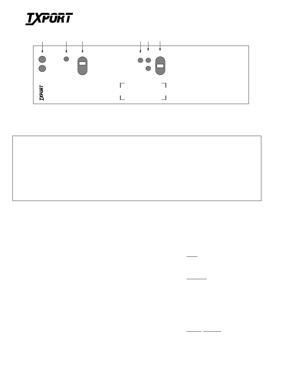
Front Panel Description
1
Status: Green LED illuminates when the unit is powered and operation is normal. The red LED illuminates when an alarm exceeding
thresholds is detected or for other unit failure.
2
ACO: Amber LED illuminates when the ACO (alarm cutoff) switch is placed in the left (On) position. It indicates that the alarm relay
contacts are forced to the No Alarms condition.
3
ACO SW: The alarm cutoff switch controls the alarm relay circuitry. When the switch is placed in the left (On) position, this circuitry is
deactivated. The ACO indicator still functions as usual.
4
Forced: Amber LED illuminates indicating that the Force switch is in either the A or B direction.
5
A / B: Either the A or B green LED illuminates indicating which input is being broadcast to the ports. Even if both Port A and Port B have
input, Port A will be selected and the A indicator illuminates.
6
Force Switch: This switch is used to force the input to either the A or B input.
AC
O
S
W
AC
O
FORCED
A
ST
A
T
US
1
060A
Br
oadcast
1060A Broadcast Card
Configuration Guide
45-00118
1.00
3
2
1
TRANSPORT
®
B
4
5
6
N
T
R
A
N
S
P
O
R
T
®