Verilink 1558A (CG) Configuration/Installation Guide User Manual
1558a aps, Configuration guide, Txport 1558a
T
R
A
N
S
P
O
R
T
®
1558A APS
Configuration Guide
Part Number 45- 00083
Revision 2.0
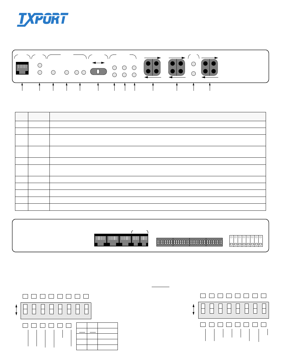
1558A Front View
AUTO T1 PROTECTION SWITCH
A
SUPV
PWR
B
STATUS
A
BYPASS
LOCKED
B
A
B
ALM
LOS
LP
A
SELECT
AUTO
PATH
B
STATUS
PATH
RX BRDG
TX BRDG
N
E
T
A
RX BRDG
TX BRDG
N
E
T
B
DTE
LOS
RX BRDG
TX BRDG
D
T
E
TxPORT 1558A
LP
-20 to -56 VDC, 200 MA
S1
DTE
COM BUS
NET B
NET A
IN
OUT
GND
–V
D
C
(
A
)
RT
N
(
A
)
–V
D
C
(
B
)
RT
N
(
B
)
Alarm
NO
C
o
mmo
n
Alarm
NC
S2
S3
S4
Switch S1
S1-7
S1-8
Boot from
Off
Off
Switches
Off
On Manager
On Off RAM
On
On
ROM
DT
E
to
NET
B
loc
k FDL
NET
to DT
E
B
loc
k FDL
DT
E
to
NET
Rege
n CRC
NET
t
o
DTE
Rege
n CRC
Ca
rd Fun
ct
io
n
Sla
v
e
AR
M
fro
m R
O
M
DTE
to
NET
P
a
ss FD
L
NET
to
DTE
P
a
ss FD
L
DTE
to
NET
P
a
ss C
R
C
NET
t
o
D
T
E
P
a
ss C
R
C
C
ard
Fu
nc
ti
on
Ma
ste
r
AR
M
fr
om
R
A
M
1
2
3
4
5
6
7
8
B
oot
Mode
B
oot
Mode
On
Off
1
2
3
4
5
6
7
8
Fra
m
ing
E
rro
rs
En
ab
le
d
LOS
En
ab
le
d
NET
A
B8
ZS
NE
T B
B8
ZS
DT
E
B8
ZS
C
SU M
ode
Fra
m
in
g Err
ors
Disa
b
le
d
LOS
Disa
b
le
d
NET
A
AMI
NET
B
AMI
DTE
AMI
Pa
th
R
eve
rt
Disa
b
le
d
DTE
Fra
m
in
g
ESF
C
SU M
ode
Pa
th
R
eve
rt
En
ab
le
d
D
T
E
F
ram
in
g
D4
En
ab
le
d
Disa
b
le
d
On
Off
Switch S2
1558A Rear View
1558A Controls and Indicators
Index
Indicator
Description
1
SUPV
The Supervisory port allows the user to connect to the 1558A via a PC running the supplied LAPS software.
2
Power
One or both of these green LEDs will be ON when a nominal power source of -20 to -56 VDC is present on the PWR A and PWR B terminals.
3
Bypass
This red LED indicates whether the unit is in a ‘bypass’ mode of operation (ON if the unit has detected a CPU watchdog operational fault and OFF
under normal operation.
4
Locked
When the 1558A has been manually forced to either the A or B path, this amber LED is on. Moving the Path Select switch back to the AUTO
position turns off this LED and restores normal APS operation.
5
A / B
These amber status LEDs indicate which of the two T1 receive paths (A or B) is presently being utilized
6
Path Select
Auto /A/B
The user can manually force and lock either the A or B path as the active path by moving this switch from the AUTO position to either the A or
B position. The 1558A is now manually locked to this path and will not switch from it, even if the selected path is or will be in a failed state.
7
Alarm
These red LEDs indicate that the user definable alarm parameters (ES, CSES, LOS, and LOF) have been met or exceeded for Path A or Path B.
8
LOS
This amber LED indicates that no T1 pulses are being detected on the receive signal paths from the network for Path A or Path B.
9
Loop
This amber LED indicates that a loop has been activated for Path A or Path B.
10
Test Jacks
Bantam test access jacks and bridge/monitor jacks are provided to gain physical access to the T1 path for NET A, NET B, and the T1 DTE path.
11
Loop /LOS
The amber ‘Loop’ LED indicates that a loop has been activated on the DTE. The red ‘LOS’ LED indicates a loss of signal on the DTE.
NOTE: For future reference, all DIP switches
on this sheet are provided with boxes to check
according to the particular user selection. Facto-
ry default settings are shown underlined.
Switches S3 and S4 are shown on the back side.
1
2
3
4
5
6
7
8
9
10
10
11
10