1558d rear view, 1558d wiring and connector information – Verilink 1558D (CG) Configuration/Installation Guide User Manual
Page 2
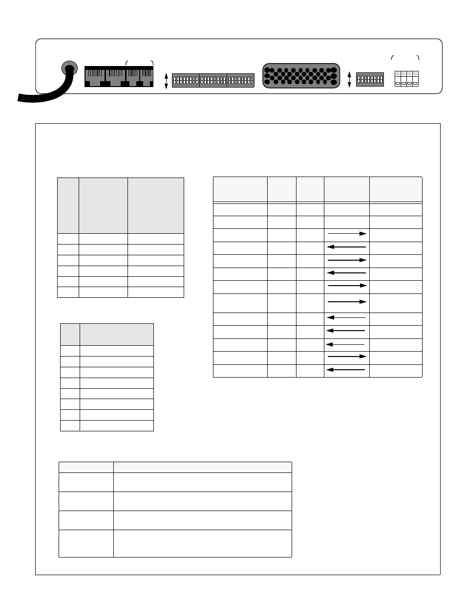
COM BUS
NET B
NET A
IN
OUT
GN
D
N.
O.
COM
N.
C.
ALARM
S1
S2
S3
S4
ON
OFF
ON
OFF
V.35
1558D Rear View
Pin
NET A & B, RJ48
Modular Connectors
1
Data In, Tip
2
Data In, Ring
3 Not
Used
4
Data Out, Tip
5
Data Out, Ring
6 Not
Used
7 Not
Used
8 Not
Used
PIN
COM BUS IN
RJ11 6-pin
Modual
Connector
COM BUS Out
RJ11 6-pin
Modual
Connector
1
Not Used
Not Used
2
Signal Ground
Signal Ground
3
Data, output
Data, Output
4
Data, input
Not Used
5
Signal Ground
Signal Ground
6
Not Used
Not Used
Function
CCITT
Name
Direction
DTE....1558
1558D V.35
(34 pin, female)
Frame Ground
101
FG
A
Signal Ground
102
SG
B
Send Data
103 A/B
SD
P, S
Receive Data
104 A/B
RD
R, T
Request to Send
105 B
RTS
C
Clear to Send
106 B
CTS
D
Data Set Ready
107 B
DSR
E
Data Terminal
Ready
108 B
DTR
H
Data Carrier Detect
109 B
DCD
F
Transmit Clock
114 A/B
TC
Y, AA
Receive Clock
115 A/B
RC
V, X
External Clock
113 A/B
EXT.TC
U, W
Test Mode
142
TM
K
Terminal
1558D Alarm Relay Terminal Descriptions
GND
(Ground)
This terminal can be used to connect the 155D to a good earth
ground
N.0.
(normally open)
External alarm equipment requiring a normally open contact
should be wired to this terminal and the common terminal
COM
(Common)
Common lead for the 1558D alarm relay contact(s)
N.C.
(normally closed)
External alarm equipment requiring a normally closed contact
should be wired to this terminal and the common terminal
1558D Wiring and Connector Information