200 esf csu, With test jacks, Productivity series – Verilink 200 (CG) Configuration/Installation Guide User Manual
Page 3: Model þ200 þesf / csu, Configuration guide
1
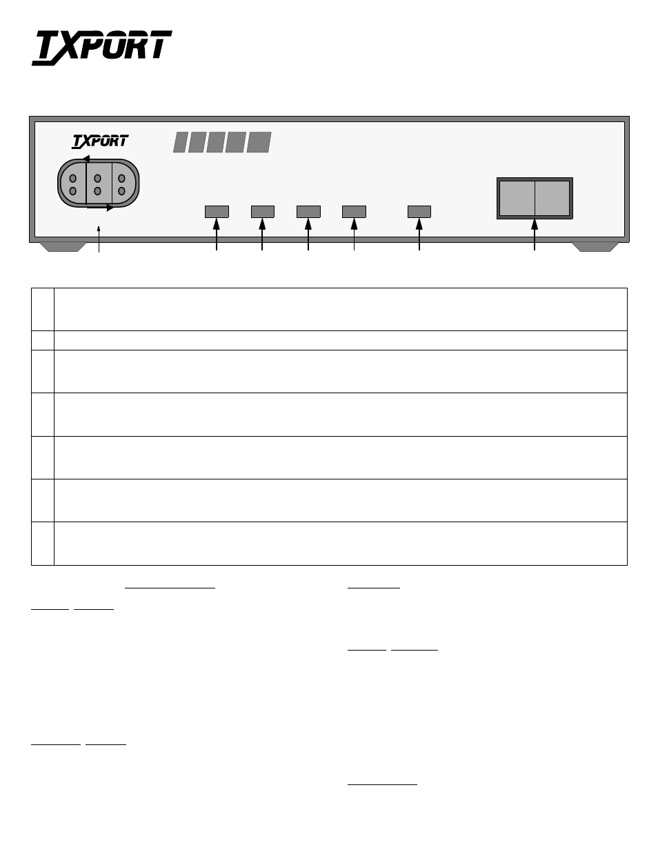
Test Access Jacks: These bantam jacks provide access to the T1 line on the DTE side as follows - the left 2 ports break connection to the unit and
make connection to the DTE, the middle 2 ports are used for monitoring the signals passing through the unit (between the DTE and the network),
and the right 2 ports break connection to the DTE and make connection to the unit in the direction of the network.
2
Power: This green LED lights when power is applied to the unit.
3
DTE T1 Status: This red LED lights a minimum of 0.1 second if the internal alarm circuitry detects any one of the following conditions from the
DTE: one or more BPVs, FBEs, CRCs, low ones density, or a loss of signal/loss of sync condition for Š 175 bit times from the network. The LED
stays lit until the unit detects Š 4 pulses in 32 bit times.
4
Network T1 Status: This red LED lights a minimum of 0.1 second if the internal alarm circuitry detects any of the following conditions from the
incoming T1 signal: one or more BPVs, FBEs, CRCs, or a loss of signal/loss of sync condition for Š 175 bit times from the network. The LED
stays lit until the unit detects Š 4 pulses in 32 bit times.
5
Far end T1 status: This red LED lights a minimum of 0.1 second if the internal alarm circuitry detects a yellow alarm signal from the far end ter-
minal equipment. This condition occurs if the far end terminal is out of sync with the T1 signal from the network. The format for a yellow alarm is
bit 2 set to 0 in each DS0 (D4 mode) or 8 ones/8 zeros in the facility data link (ESF mode).
6
Loop: This amber LED lights under the following conditions: the manual loop switch is placed in the ‘LOOP’ position, the unit receives an
inband loop code for > 5 seconds, or the unit receives an FDL loop message (PLB or LLB). The LED does not light if the test switch is placed in
the ‘NORM’ position or if an inband or FDL unloop code is received for >5 seconds.
7
Test Switch: This 2- position switch is used for local testing. When placed in the local loop mode (LOOP), the unit loops the signal from the cus-
tomer equipment (DTE IN) back to the customer equipment (DTE OUT). It also loops the received signal from the T1 facility (NET IN) back to the
T1 facility (NET OUT). When moved back to ‘NORM’, the local loopback is removed.
200 ESF CSU
Configuration Guide
Part Number 45-00043
Rev 1.00
LOOP
NORM
PWR
DTE
NET
LOOP
FAR
PRODUCTIVITY
SERIES
TxPORT 200 Front Panel
SPECIFICATIONS
Network Interface
Line Rate:
1.544 Mb/s (±50 bps)
Line Framing:
D4 or ESF
Line Code:
AMI or B8ZS
Line Impedance:
balanced 100
Ω
(±5%)
Input Signal:
DS1, +1 to -30 dB (ALBO)
Output Signal:
3.0 V, ±15%, base-peak into 100 ¾
Line Build Out:
0, -7.5, -15, &-22.5 dB attenuation
Line Protection:
1000 V lightning, fused input/output
Jitter Control:
per TR62411 &T1.403
Pulse Density:
per TR62411
Equipment Interface
Line Rate:
1.544 Mb/s (± 50 bps)
Line Framing:
D4 or ESF
Line Code:
AMI or B8ZS
Line Impedance:
balanced 100
Ω
(± 5%)
Input Signal:
DSX1 to 655 feet
Output Signal:
Selectable DSX1 signal level from 0 to 655 feet
Line Protection:
1000 V lightning, input/output
Mechanical
Mounting:
desktop or wall
Dimensions:
1.75" H, 6.8" W, 10.5" D
Weight:
2 lbs.
Industry Standards
FCC Compliance:
Part 15 Subpart B, Class A
FCC Part 68 Reg:
FXKUSA- 75742 - DE- N
NRTL
UL 1459
CSA Certified:
LR62298
DOC /CSO3:
1653 5663 A
TR 54016
September 1989
TR 62411
ANSI T1.403
Environmental
Operating Temp:
0° to 50°C (32° to 122°F)
Storage Temp:
- 20° to 85°C (-4° to 185°F)
Humidity:
95% max (non- condensing)
Front Panel Description
T
R
A
N
S
P
O
R
T
®
MODEL þ200 þESF / CSU
NET
MON
DTE
1
7
6
5
4
3
2
T
O
D
T
E
T
O
N
E
T
with TEST JACKS
T
R
A
N
S
P
O
R
T
®