Verilink 2000 ESF CSU Standalone (CG) Configuration/Installation Guide User Manual
2000 esf csu, Configuration guide, Specifications
LO
C
FA
R
AC
O
S
W
N
E
T
D
T
E
T
S
T
LL
B
PL
B
TS
T
ER
R
FRM
NET
MO
N
TO
DT
E
TO
NET
MON
FRM
DTE
DENSITY
BV
/C
R
/FE
LO
S
/O
O
F
AIS
REM
A
LM
LO
C
A
LM
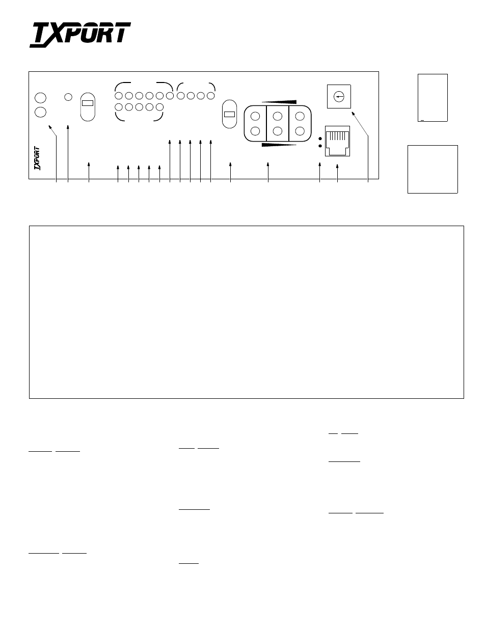
Front Panel Description
1
Status: The green LED lights when the unit is powered and operation is normal. The red LED lights if an alarm exceeding thresholds is detected.
2
ACO: This yellow LED lights if the Alarm Cut Off switch is placed in the left ON position. It indicates that the alarm relay contacts are disabled.
3
ACO SW: This switch controls the alarm relay circuitry. If the switch is placed in the left ON position, this circuitry is deactivated.
4
BV/CR/FE: This LED lights one second for each second that has an occurrence of bipolar violations, cyclic redundancy check errors, or frame bit errors.
5
LOS /OOF: This LED blinks with loss of signal (LOS) from the network or DTE. It lights constantly when an out of frame (OOF) condition is detected.
6
AIS: This LED lights if an unframed all ones condition (alarm indication signal) is detected from the network or equipment.
7
REM ALM: This LED lights constantly when a yellow alarm signal is received from the far end.
8
LOC ALM: This LED lights when a local alarm exceeding alarm thresholds exists. It remains lit until the Alarm Reset Timer period ends.
9
DENSITY: This LED lights when the ones density requirement of the received equipment signal is below the minimum.
10 LLB: This LED lights continuously when the network interface is in a line loopback. It flashes when the DTE interface is in a line loopback.
11 PLB: This LED lights continuously when the network interface is in a payload loopback.
12 TST: This LED lights continuously during a far or local test. It flashes when loop codes are transmitted at the start of a far test and when unloop codes are
transmitted at the end of a far test.
13 ERR: This LED lights for one second when BERT pattern errors are received during a Far test.
14 Test Switch: This switch is used for local testing. If transmitting IBLC, the test LED blinks. If transmitting a test pattern, it lights continuously.
15 Test Jacks: Provides access to the T1 line on the DTE side – the top two jacks break connection to the DTE and make connection to the unit in the direction of the
network, the middle two ports monitor the signals passing through the unit, and the bottom two ports break connection to the un it and make connection to the DTE.
16 Activity LEDs: These two small, recessed LEDs are provided to indicate supervisory and NMS port activity.
17 SUPV: This 6 - pin supervisory jack provides direct terminal access for CSU control and gathers status/facility performance data. Refer to the table above.
18 Pattern Select: This rotary switch determines the BERT pattern sent by the unit when the test switch (item 14) is in the FAR position. Refer to the table above.
Specifications
Network Interface
Line Rate:
1.544 Mbps, ± 50 bps for internal
clock, ± 200 bps in through mode
Line Impedance:
balanced 100
Ω
(± 5%)
Input Signal:
DS1, 0 to -27 dB (ALBO)
Output Signal:
3.0 V (± 15%), base-peak into 100
Ω
Line Build Out:
0, -7.5, -15, and -22.5 dB attenuation
Line Protection:
1000 V lightning, fused input/output
Jitter Control:
per TR 62411 and T1.403
Pulse Density:
per TR 62411
Equipment Interface
Line Rate:
1.544 Mbps, ± 50 bps for internal
clock, ± 200 bps in through mode
Line Impedance:
balanced 100
Ω
(± 5%)
Input Signal:
DSX1 to -6 dB
Output Signal:
Selectable DSX1 level from 0 to 655
feet in six incremental levels
Line Protection:
1000 V lightning, fused input/output
Clock Sources
Internal:
25 ppm (1.544 MHz), 1.5 ppm option
Receive:
100 ppm, 1.544 MHz
External (optional): -27 dB T1 signal @ 1.544 MHz
Time of Day:
Internal clock battery backup set by
network manager
Diagnostics
Loopbacks:
Line loopback and payload loopback
on the network interface; Line loop-
back on the DTE interface
Network BERT:
QRSS, 63, 511, 2047, 2
15
, 2
20
, 2
23
,
1 in 8, 3 in 24, Alternate, and Clear
Alarms
Activation:
Programmable thresholds
Reporting:
NO or NC contacts, NMS,
front panel LEDs, internal buzzer
Contact Ratings:
UL 0.3 A @ 110 VAC
1.0 A @ 30 VDC
DC Power
19 VDC to 60 VDC range, 4.3 W, 15 BTU
Mechanical
Mounting:
desktop, wall, horizontal/vertical rack
Dimensions:
1.72" W, 6.8" H, 10.5" D
Weight:
2 lbs
Industry Standards
FCC Compliance:
Part 15 Subpart B, Class A
FCC Part 68 Reg. #:
FXKUSA-74451- DE-N
UL Approved
E110448
CSA Certified:
LR 98859
IC /CSO3:
1653 5188 A
TR 54016
TR 62411
ANSI T1.403
Pattern Select
0 QRSS
1 1 in 8
2 3 in 24
3 2
15
-1
4 2
20
-1
5 Clear
Supervisory Port
1
Control Out
2
Signal Ground
3
Data Out
4
Data In
5
Signal Ground
6
Control In
T
R
A
N
S
P
O
R
T
®
2000 ESF CSU
Configuration Guide
45-00056
Rev 4.0
3
4
AC
O
2
5
6
7
8
9 10 11 12 13
14
15
17
16
18
2000
CSU
S
U
P
V
1
6
P
A
T
SEL
5
1
7
9
0
6
8
2
3
4
TRANSPORT
®
1
ST
A
T
US