Verilink 2048 (CG) Configuration/Installation Guide User Manual
2048 pmu/ntu, Configuration guide
LO
C
FA
R
AC
O
S
W
N
E
T
D
T
E
T
S
T
LLB
PL
B
TST
ERR
FR
M
NET
MON
TO
DTE
TO
NET
MO
N
FRM
DTE
BV
/C
R
/FE
LO
S
/LO
F
AIS
RE
M
A
LM
LO
C
A
L
M
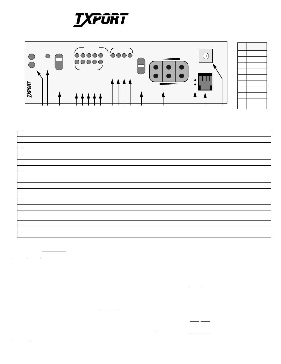
1 Status: The green LED lights when the unit is powered and operation is normal. The red LED lights if an alarm exceeding thresholds is detected.
2 Alarm Cut Off: This yellow LED lights if the Alarm Cut Off switch is placed in the left ‘ON’ position. It indicates that the alarm relay contacts are disabled.
3 ACO Switch: This switch controls the alarm relay circuitry. If the switch is placed in the left ‘ON’ position, this circuitry is deactivated.
4 BV/CR/FE: This LED lights 1 second for each second that has an occurrence of bipolar violations, cyclic redundancy check errors, or frame bit errors.
5 LOS /LOF: This LED blinks with loss of signal (LOS) from the network or DTE. It lights constantly when a loss of frame (LOF) condition is detected.
6 AIS: This LED lights if an unframed all ones condition (alarm indication signal) is detected from the network or equipment.
7 Remote Alarm: This LED lights constantly when a remote (yellow) alarm signal is received from the far end.
8 Local Alarm: This LED lights when a local alarm exceeding alarm thresholds exists. It remains lit until the Alarm Reset Timer period ends.
9 LLB: This LED lights continuously when the network interface is in a line loopback. It flashes when the DTE interface is in a line loopback.
10 PLB: This LED lights continuously when the network interface is in a payload loopback.
11 TST: This LED lights continuously during a far or local test. It flashes when loop codes are transmitted at the start of a ‘far’ test and when unloop codes are
transmitted at the end of a ‘far’ test.
12 ERR: This LED lights for 1 second when BERT pattern errors are received during a ‘Far’ test.
13 Test Switch: This switch is used for local testing. If transmitting IBLC, the test LED blinks. If transmitting a test pattern, it lights continuously.
14 Test Jacks: These jacks provide access to the T1 line on the DTE side – the top 2 jacks break connection to the DTE and make connection to the unit in the direction
of the network, the middle 2 ports monitor the signals passing through the unit, and the bottom 2 ports break connection to the unit and make connection to the DTE.
15 Activity LEDs: These 2 small, recessed LEDs are provided to indicate supervisory and NMS port activity.
16 SUPV: This 6 - pin supervisory jack provides direct terminal access for PMU control and to gather status/facility performance data.
17 Pattern Select: This rotary switch determines the BERT pattern sent by the unit when the test switch (Item 14) is in the ‘FAR’ position. Refer to the table above.
Specifications
Network Interface
Line Rate:
2.048 Mb/s, ± 50 ppm, PCM- 30
Multi- frame Type: CAS and /or CRC4, or none
Line Code:
AMI or HDB3
Connection:
120 ¾ balanced or 75 ¾ unbal.
Backplane:
DB15, Twin - axial, and BNC
Output Signal:
75 ¾ mark 2.37 V, space 0 ±0.237 V
(per G.703)
120 ¾ Mark 3 V, Space 0 ± 0.3 V
Line Build Out:
0, - 7.5, -15 dB switch settings
Input Signal:
75 ¾ mark 2.37 V, space 0 ± 0.237 V
(per G.703)
120 ¾ Mark 3 V, Space 0 ± 0.3 V
attenuated by 0 to - 27 dB (ALBO)
Jitter Attenuation: per CCITT G.823
AIS:
Unframed or framed all ones, or
(user selectable)
line loopback
Overvoltage:
1000 V minimum protection
Equipment Interface
Line Rate:
2.048 Mb/s, ± 50 ppm, PCM- 30
Multi- frame Type: CAS and /or CRC4, or none
Line Code:
AMI or HDB3
Output Signal:
75 ¾ mark 2.37 V, space 0 ±0.237 V
(per G.703)
120 ¾ Mark 3 V, Space 0 ± 0.3 V
Pulse Width:
244 ns, nominal
DTE Input Signal: 75 ¾ mark 2.37 V, space 0 ±0.237 V
(per G.703)
120 ¾ Mark 3 V, Space 0 ± 0.3 V
attenuated by 0 - 6 dB @ 1024 kHz
Connection:
120 ¾ balanced or 75 ¾ unbalanced
Backplane:
DB15, Twin - axial, and BNC
AIS:
Unframed or framed all ones, LLB
Overvoltage:
1000 V minimum protection
Diagnostics
Line Loopback:
Signal regeneration only
Payload Loopback: Signal regenerated with new frame
synchronization and CRC4
BERT:
63, 511, 2047, 2
15
(default), 2
20
,
2
23
, QRW, and ALT
BERT Activation: Front panel switch, user selection of
patterns via command. Pattern sync
/bit errors reported via command.
Loopback Control: Inband loop up, 00001 for Ý 5 sec
Inband loop down, 001 for Ý 5 sec
User enable/disable, Manual loop
back switch, FDL loopback comnd.
PTT and EM8000 Full ESF performance monitoring
through 6 - pin RJ11 terminal port,
and via FDL in selected national bit
Alarms
Contacts:
Normally Open or Normally Closed
(screw terminal connection)
Activation:
Programmable
Reporting:
Through TxPORT EM8000
Cut Off:
Manual, 2 - position switch
Local Power
- 48 VDC (± 10 %), 75 mA max (screw terminal)
Mechanical
Mounting:
Wall, horizontal or vertical rack
Dimensions:
1.75" W, 6.0" H, 11.75" D
Weight:
1 pound
T
R
A
N
S
P
O
R
T
®
2048 PMU/NTU
Configuration Guide
3
4
AC
O
2
5
6
7
8
9 10 11 12
13
14
16
15
Front Panel Description
20
48
S
U
P
V
1
6
PAT
S
E
L
5
1
7
9
0
6
8
2
3
4
TRANSPORT
®
1
ST
A
T
US
PM
U
/N
T
U
Pos
Pattern
0
QRW
1
2
7
2
2
9
3
2
15
4
2
20
5
2
23
6
1 in 8
7
3 in 24
9
PROM
Download
Pattern Select
17
Part # 45-00031
Rev 1.00