Verilink 301 (CG) Configuration/Installation Guide User Manual
Productivity series 301, 301 e1 ntu (csu/dsu), Configuration guide
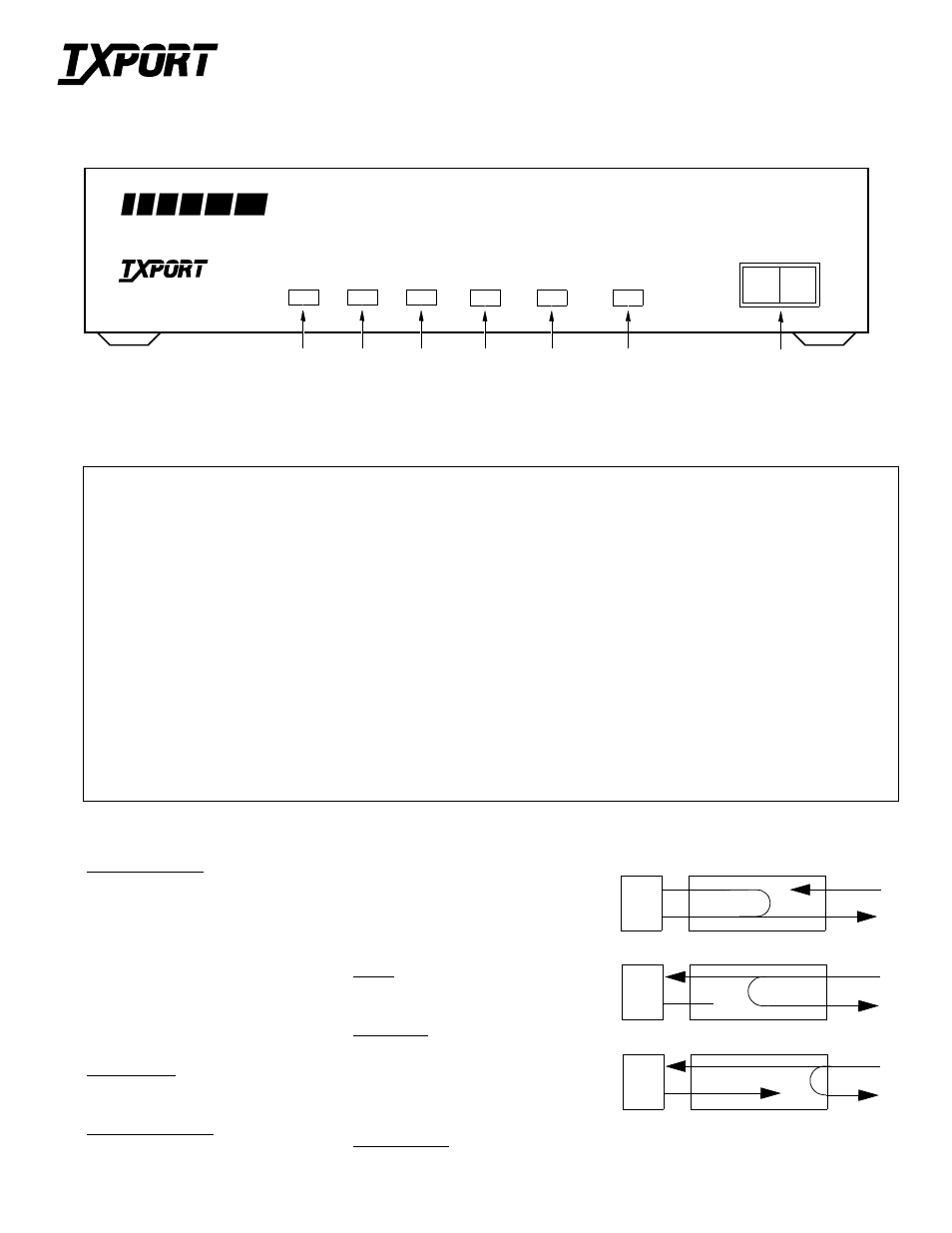
Front Panel Description
1
SD
Green
Illuminates when the Send Data lead is a mark and is Off when the lead is a space. The LED varies from full intensity to Off depend-
ing on the relative number of marks and spaces.
2
RD
Green
Illuminates when the Receive Data lead is a mark and is Off when the lead is a space. The LED varies from full intensity to Off
depending on the relative number of marks and spaces.
3
IN SYNC
Green
Illuminates when the unit is in frame synchronization with the E1 line.
4
ERROR
Red
Illuminates when the internal alarm circuitry detects any of the following conditions from the incoming E1 signal: BPVs, FBEs,
CRCs, loss of signal/loss of sync, or more than 175 zeros.
5
REMOTE
Red
Illuminates when the internal alarm circuitry detects a remote alarm signal from the far end terminal equipment. This occurs when the
far end terminal is out of sync with the E1 signal from the network.
6
TEST
Amber
Illuminates when the unit is in test mode by either a manual loop switch or a test command received from the facility. When illumi-
nated, circuit 142 (TM), pin K at the digital interface is active (On).
7
RL
Initiates an automated V.54 remote loop and BERT sequence of assigned data channels. The TEST LED turns green if the test is successful (the
far end unit loops and returns the data error free with the V.54 code) and red if errors are detected in the test.
NORM
Switching from LL to NORM takes the unit out of test mode. Switching from RL to NORM transmits the V.54 deactivate code.
Places the unit in a local loop mode. Data from the DTE is looped back to the DTE and is also transmitted to the network (data from the network
is open).
LL
T
R
A
N
S
P
O
R
T
®
301 E1 NTU (CSU/DSU)
Configuration Guide
45- 00106
2.0
Specifications
Network Interface
Line Rate:
2.048 Mbps (±50 ppm)
Line Framing:
CCS or CRC4
Line Code:
AMI or HDB3
Line Impedance:
Balanced 120
Ω
(±5%)
Unbalanced 75
Ω
(available)
Input Signal:
+6 to -43 dB
Output Signal:
3.0 V (±15%) base-peak into 120
Ω
Line Protection:
Per ITU-T K.15, K.21, K.32
Jitter Control:
ITU G.703
Pulse Density:
ITU G.703
V.35 Interface
Data Rate:
Synchronous, Nx56 or Nx64 kbps
Clocking:
Internal or external
Industry Standards
FCC Compliance: Part 15 Subpart B Class A
FCC Part 68 Reg: Not Applicable
CAN/CSA:
C22.2 No. 950-95
IC/CSO3:
Not Applicable
UL:
1950 Third Edition
G.703
July 1995
G.704
September 1989
G.706
April 1991
G.732
1988
G.823
1993
Power
DC Power:
External
Connection:
5-pin DIN
Mechanical
Mounting:
Desktop, wall, or vertical rack
Dimensions:
1.75 inches (4.44 cm) High
6.8 inches (17.27 cm) Wide
10.5 inches (26.67 cm) Deep
Weight:
2 pounds (0.907 kg)
Environmental
Operating Temp:
32
°
to 122
°
F (0
°
to 50
°
C)
Storage Temp:
-4
°
to 185
°
F (-20
°
to 85
°
C)
Humidity:
95% maximum (non-condensing)
Loops
DTE
NET
Local Loopback
DTE
NET
Remote Channel Loop (V.54)
DTE
CSU Line Loop (Inband)
RL
LL
SD
RD
IN SYNC
TEST
PRODUCTIVITY
SERIES
301
7
6
3
2
1
E1 CSU/DSU
T
R
A
N
S
P
O
R
T
®
ERROR
4
REMOTE
5
NORM
NET